-9-
Setting Obstruction Margin
The Obstruction Force Margin sensitivity is extremely
important for user safety. Make sure that where possible
the minimum (or default) force required to allow the
door to travel without phantom reversing is used. Smart
Openers strongly recommend that the door is properly
serviced rather than increasing the force margin to
compensate (Factory Default = Light).
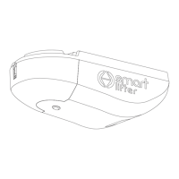
1 Press SET for 7 secs until the red LED will ash and
the opener will beep to indicate the current obstruction
margin setting and the yellow LED will indicate the PE
Beam status.
2 Press CODE to change the force margin setting - the
red LED will ash to indicate your new setting:
1 Flash = Light
2 Flashes = Medium
3 Flashes = Maximum
3 If you do not need to alter the photo beam setting as
per below, press SET to save and exit.
Setting Photo Beam Mode
Note: A functioning photo electric safety beam must be
installed before Photo Beam Mode set to ON.
Photo Beam Mode offers added safety protection by
stopping the door from closing if the beam is tripped.
Smart Openers strongly recommend the installation of a
PE safety beam to protect persons and property
(Factory Default = Off).
Note: If the photo beam has already been connected and
you are still in set up mode from the obstruction
margin procedure above continue to step 3.
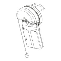
1 Connect PE Beam cable to controller terminal block
as per Fig. 19.
2 Press SET for 7 secs until the red LED will ash and
the opener will beep to indicate the current obstruction
margin setting and the yellow LED will indicate the PE
Beam status.
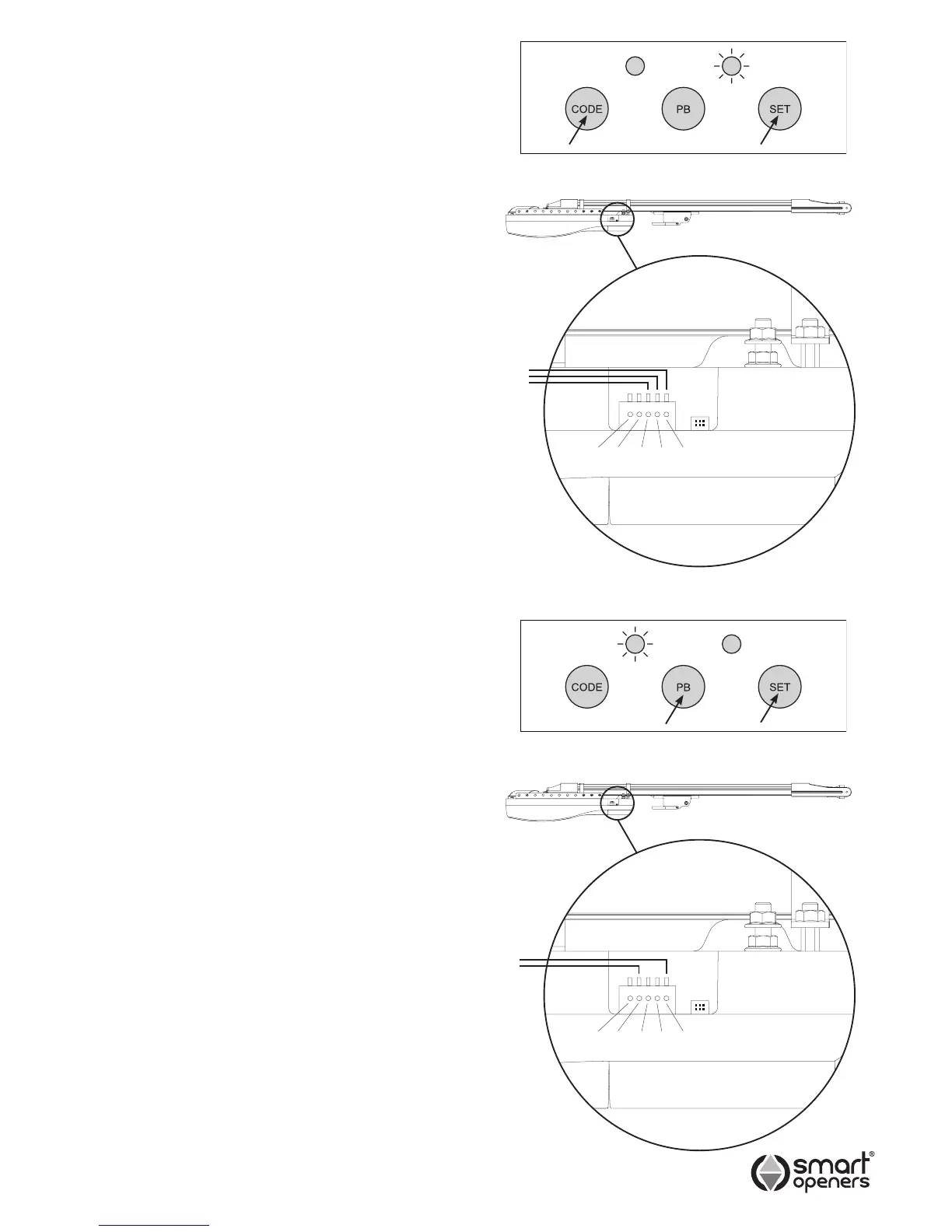
3 Press PB to change to ON, the yellow LED will
illuminate (Fig. 20).
4 Press SET to save and exit.
Connecting External Push
Button
Note: The connection must be a voltage free dry contact.
Connect the two wires from your push button to the PB
and GND terminals as per Fig. 21.
DO NOT connect to input power - this will blow the board
and void the warranty.
© September 2011 Smart Openers Pty Ltd
Fig. 18
Fig. 20
Fig. 19
Fig. 21
 Loading...