T4 (053B) Series Installation Guide
CD354/220116 Smartscan Ltd
Appendix 3 - Mirrors
Reflector mirrors can be provided enabling two or three sides of a machine to be
safeguarded with, what is effectively a single light curtain.
When mirrors are employed it is essential that the mounting of the transmitter unit,
receiver unit and mirrors themselves are sufficiently rigid. Alignment becomes
increasingly critical as the range and number of mirrors increase. Mirrors cause a
reduction in optical efficiency, reducing the effective range. A guide to the
practicality of using mirrors is given below.
Range of the
light curtain
Maximum range
through 1 mirror
Maximum range
through 2 mirrors
Based upon a 053B612
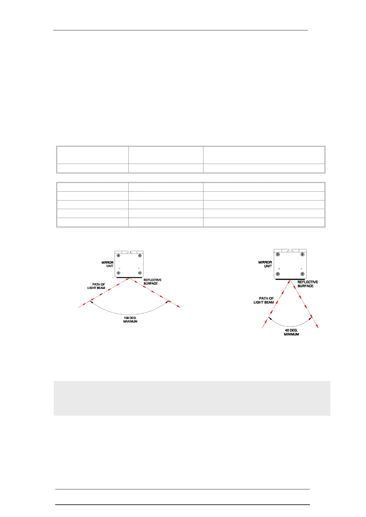
The angle of the infrared beams from the light curtain striking the reflective
surface must be within defined limits as per the drawings above. See Fig. D in
this guide.
Perimeter curtains will be easier to align, curtains over 900mm may be more
difficult to align. Check with the Smartscan technical department prior to ordering
for a particular application, support@smartscan.com, Tel: +44 (0) 1536 401 313,
Fax: +44 (0) 1536 268 954
Note The mirror length must be a minimum of 100mm longer than the detection
zone (K) of the light curtain to be installed e.g. 50mm above and 50mm below
either end of the light curtains detection zone (K).