Black OUT1
White N.C.
Blue DC (−)
18 to 30 VDC
+
−
Main circuit
Black OUT1
White N.C.
Blue DC (−)
+
−
Load
Brown DC (+)
Black OUT1
White OUT2
Blue DC (−)
18 to 30 VDC
+
−
Brown DC (+)
Black OUT1
White External input
Blue DC (−)
18 to 30 VDC
+
−
Brown DC (+)
Black OUT1
White Analog output
Blue DC (−)
18 to 30 VDC
+
−
Brown DC (+)
Black OUT1
White OUT2
Blue DC (−)
+
−
Brown DC (+)
Black OUT1
White External input
Blue DC (−)
+
−
Brown DC (+)
Black OUT1
White Analog output
Blue DC (−)
+
−
Main circuitMain circuitMain circuit
Main circuit
Main circuit
Main circuit Main circuit
Main circuit
Load
Load
LoadLoad
Load
Load
Load
Load
Load
Load Load
U
U
U
U
U
U
U
U
U
U
U
IO-Link
master
L−
C/Q
L+
Blue L−
White Other
Black C/Q
Brown L+
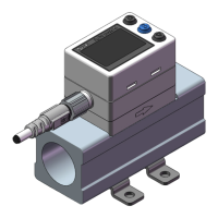
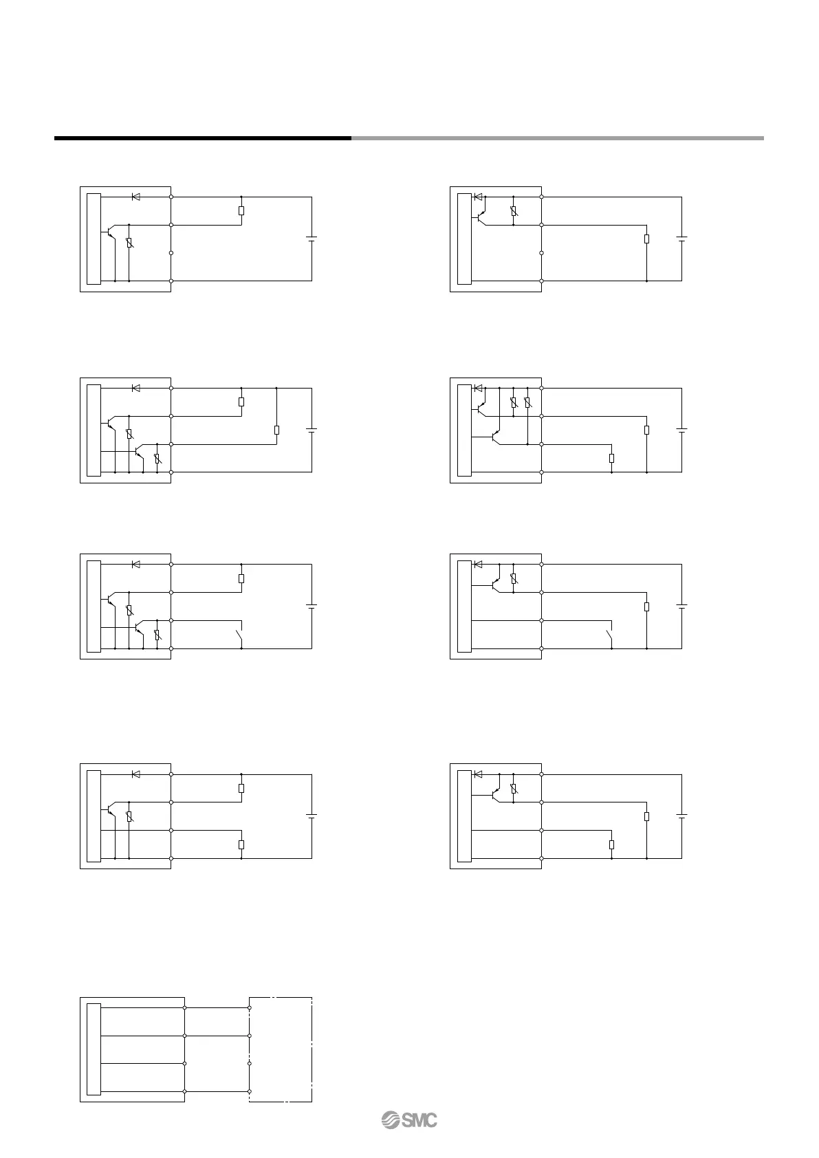
Internal Circuits and Wiring Examples
PF2M7mm-m-Lm-mmm
NPN output type
PNP output type
Max. applied voltage: 30 V, Max. load current: 80 mA,
Internal voltage drop: 1.5 V or less
Max. load current: 80 mA, Internal voltage drop: 1.5 V or less
Max. load current: 80 mA, Internal voltage drop: 1.5 V or less
Max. applied voltage: 30 V, Max. load current: 80 mA,
Internal voltage drop: 1.5 V or less
PF2M7mm-m-L2m-mmm
NPN 2 output type
PNP 2 output type
PF2M7
mm-m-L3/4m-mmm
L3: NPN + Analog voltage output type
L4: NPN + Analog current output type
L3: PNP + Analog voltage output type
L4: PNP + Analog current output type
When used as an IO-Link device
Max. applied voltage: 30 V, Max. load current: 80 mA,
Internal voltage drop: 1.5 V or less
NPN + External input type PNP + External input type
Max. applied voltage: 30 V, Max. load current: 80 mA,
Internal voltage drop: 1.5 V or less
L3: Analog output: 1 to 5 V or 0 to 10 V can be selected.
Output impedance: 1 kΩ
L4:
Analog output: 4 to 20 mA
Load impedance: 50 to 600 Ω
Max. load current: 80 mA, Internal voltage drop: 1.5 V or less
L3
:
Analog output: 1 to 5 V or 0 to 10 V can be selected.
Output impedance: 1 kΩ
L4:
Analog output: 4 to 20 mA
Load impedance: 50 to 600 Ω
Max. load current: 80 mA, Internal voltage drop: 1.5 V or less
17
PF2M7(-L) Series
 Loading...