24
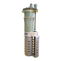
g. Assemble the tap selector and the diverter switch’s odd & even cables
Take out the cables inside the diverter switch’s packing box and use 25 pieces of M8 and 35 pieces of M10
bolts according to the serial number to connect the diverter switch’s and tap selector’s wiring heads
serial number: The serial number is printed on the terminals of the tap selector of each type of switch and
on the terminals of the diverter switch, here, for example, the three-phase switch has the words U1, V1 and
W1 printed on its terminals, please use the wires with the corresponding words for connection.
Note:
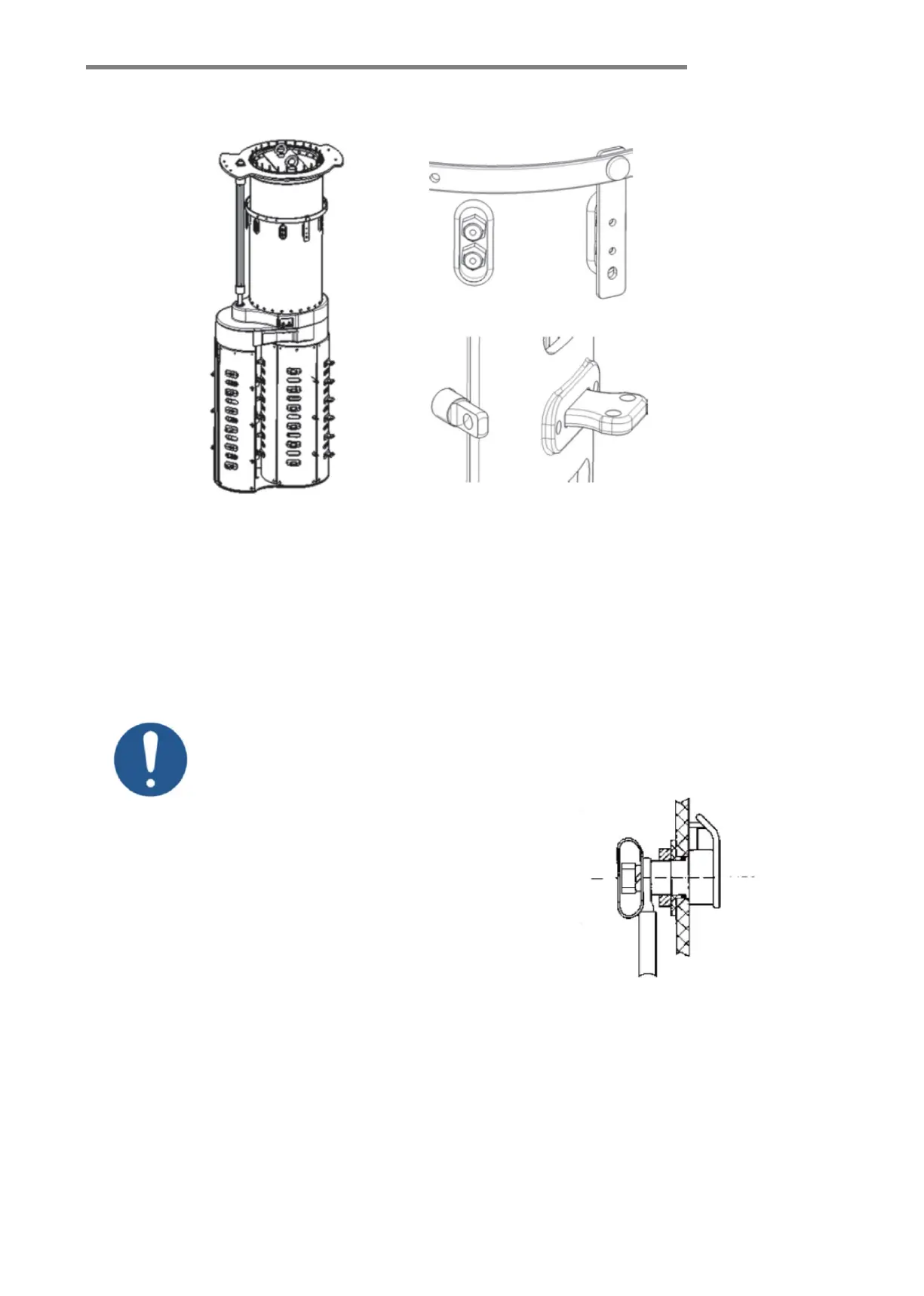
a. Remember to align the cables directly with the contact on the
diverter switch cylinder, and not to sandwich the shielding cap
between them two (see Figure-6-11).
b. Connection of all lead-out cables must be carefully carried out
and must follow specified tightening torques. The bolt connection
must be 100% reliable, and the terminal part must be shielded with
the shielding caps which are supplied with the tap-changer.
c. When connecting the tap selector and the diverter switch, be
careful not to damage the insulation layer of the cable package.
d. When working on tap-changer, MDU or other components,
make sure that they are all firmly fixed! Every part must be prevented from accidentally tipping over!
e. After the cables are connected with bolts, fasten the screen cap.
Note! The tap changer must be in an accurate vertical position in terms of the support structure. (Max. 2°
vertical position deviation). The installation of the tap changer’s supporting structure must ensure that the tap
changer can be lifted 5 to 20 mm to its final position after the bell-type transformer tank cover is closed.