• 13 •
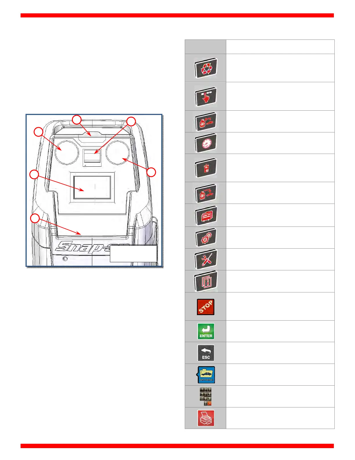
CONTROL PANEL
Refer to Fig. 5:
1) Low pressure gauge
2) High pressure gauge
3) Printer
4) 7” touch color display
5) Tool tray
6) Status light
LIGHT SIGNALS
The machine is provided with a STATUS Light (ref 6, Fig. 5).
Light signals are the following:
GREEN (STEADY): Unit ready
GREEN (FLASHING): Action completed
YELLOW: Unit working
RED: Needs attention or there is a problem
DISPLAY ICONS
ICON DESCRIPTION
AUTOMATIC PROCEDURE: Activates a menu
that helps the user set up an automatic
recover/vacuum/leak test/charge sequence
MANUAL PROCEDURE: Activates a menu
that helps the user to perform a manual
operation
RECOVERY: Activates a menu that helps the
user to perform a recovery/recycling phase
VACUUM: Activates a menu that helps the
user to perform a vacuum phase
PAG/DYE INJECTION: Activates a menu that
helps the user to perform a PAG/DYE
injection followed by a charge phase
CHARGE: Activates a menu that helps the
user to perform a gas charge phase
SERVICES: Activates services menu
SETUP: Activates the setup menu of the
service station
MAINTENANCE: Activates the maintenance
menu of the service station
INFO: Activates a menu that contains all the
information of the service station
STOP: Terminates a procedure or operation,
silences the audible alarm or returns to the
previous screen
ENTER: Confirm a procedure or operation
shown on the display
ESC: Return back to previous menu
DATABASE: Activate database menu
KEYPAD: Numerical keypad (includes an
alphabet that is used to text messaging)
PRINTER: To print the receipt of the
procedure
FIG. 5
4
2
1
5
3
6