129
Scope Multimeter Operations Operations
4. Select the Trace Probe icon to open the menu.
5. Highlight a probe on the list and select OK to close the window.
6. Select the Trace Scale icon to adjust the vertical scale, of the display.
A dropdown menu opens, menu options vary depending upon which test lead is selected.
7. Select a trace scale option, then close the window.
8. Select or deselect the trace characteristic items as needed:
– Displayed—this trace is on screen when checked, and not visible when not checked.
– Inverted—signal polarity is reversed when checked, normal when not checked.
– Coupling AC—check when sampling an AC signal, do not check for DC signals.
– Peak Detect—use when trying to capture a fast event or signal glitch.
9. The scope samples the signal and internally calculates the best way to display it when Auto
Find is selected. A scale and the vertical position for the zero line of the trace that allows the
whole waveform to fit on the screen is established when Auto Find is selected. If Auto Find is
selected on the trigger channel, it also sets the trigger level halfway between the minimum and
maximum value of the sampled signal to provide a stable waveform.
10. The baseline position is the zero line of the trace, use the slider and arrows to adjust it.
11. Select Back to return to the Preferences dialog box, or select Exit to close the dialog box and
return to the scope.
Sweep Controls
Sweep is the amount of time represented by the screen, or the horizontal scale of the display.
z To adjust Sweep controls:
1. Select Setup from the Scope Multimeter toolbar.
The Scope Multimeter Preferences dialog box opens.
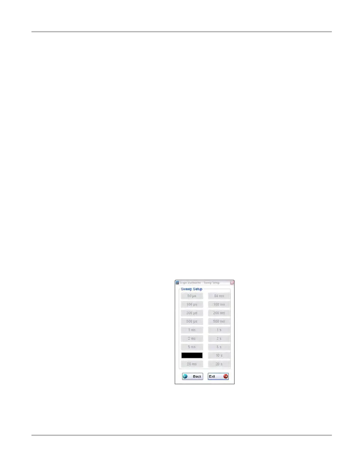
2. Select Sweep to open the sweep dialog box (Figure 9-12)
Figure 9-12 Sample Sweep Setup dialog box
3. Choose an option from the list.
4. Select Back to return to the Preferences dialog box, or select Exit to close the dialog box and
return to the scope.
 Loading...