© Trynex International 2009 L1040
7 — 16
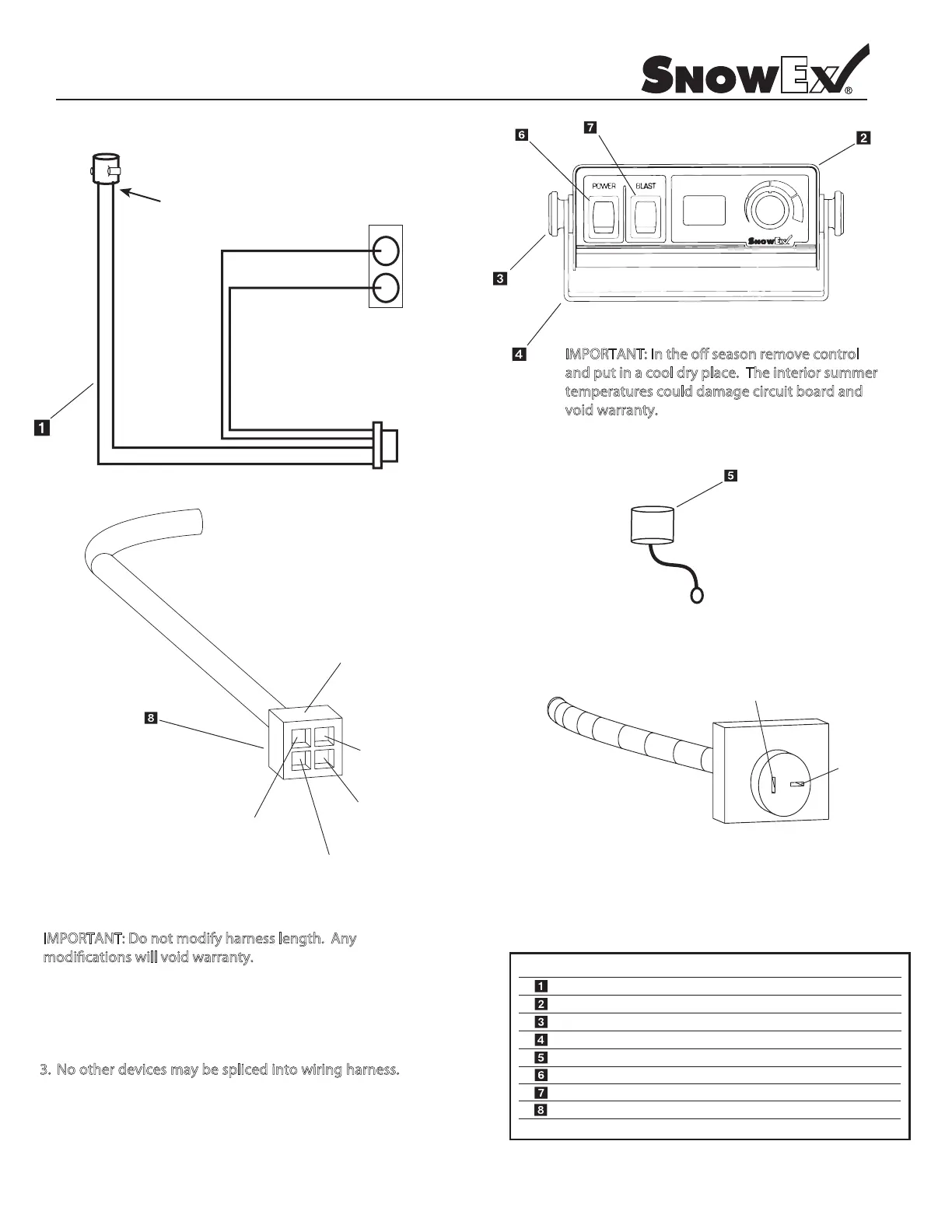
Model # SP-1075/SP-575
Control and Harness Diagram
.ytQ noitpircseD .oN traP yeK
D 6114 Wiring Harness - 24’ 1
D 6230 1075/575 Variable Speed Controller 1
2 bonK tekcarB 4216 D
D 6123 Controller Mounting Bracket 1
D 6118 Dust Cover 1
D 6242 3 Terminal Contol Power Switch 1
Special Notes:
1. All external connections must have dielectric grease.
2. Read lead labels before attaching to power source or ground.
o o ev p o
4. Any repairs to wiring harness must be done with heat
shrink butt connectors.
5. If inline fuse is installed, use a 35 amp time delay type
or a circuit breaker (575 and 1075).
- NEG
Black
+ POS
Red
Connector
(rubber molded type)
Black Lead (-) Neg
Red Lead (+) Pos
Battery
Anderson
Connector
VEHICLE
BUMPER PLUG
Black
Positive (+)
Red
Negative (–)
M O A ov o
a p a o p o
p a ag bo
vo a a
D 6241 Blast Switch 1
D 6170 Anderson Connector With Leads 1
Anderson Block
(4) Pos
INPUT POWER
Red Positive (+)
INPUT GROUND
Black Negative (–)
SPINNER OUTPUT POWER
Red Positive (+)
SPINNER OUTPUT GROUND
Black Negative (–)
CONTROL
HARNESS PLUG
SPINNER CIRCUIT
D 6344 Dielectric Grease - 1 1/2 oz. (not shown) 1
O o o d f l
d c ll o d