11
EN
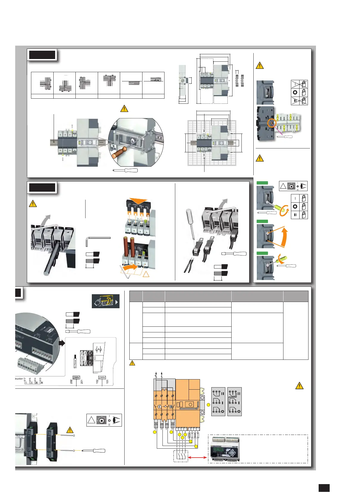
Step 1
Step 2
Step 3
1: Position I order
2: Position II order
3: Position 0 order
4: Power supply I (230 VAC)
5: Power supply II (230 VAC)
6: Voltage tap
7: Auxiliary contact block -
1 NO/NC contact per position I,
0, II (1x factory fitted)
A: Bridging bar (accessory)
B: Single-phase voltage sensing tap
(accessory)
C: F1/F2 = fuse 10 A gG
* Remote orders from ATS
controller such as ATyS C20/
C30/C40 or PLC, BMS, etc.
LOAD
5 A AC1
250 Vac
22 24 21
11 14 12
01 04 02
1309 0001
5 A AC1
250 Vac
22 24 21
11 14 12
01 04 02
1309 0011
Slotted head 3mm 0,5 Nm
0,5 to 2,5 mm²
0,5 to 1,5 mm²
6 mm
STEP 1
The ATyS M is delivered with
padlocking configured to the
O position.
To allow padlocking in all
positions (I - O - II), configure
the ATySM as follows before
installation. (Screw is located
at the back of the product).
STEP 3
Posidriv PZ2
2,2 lb-in 0,25 Nm
Posidriv PZ2
Posidriv PZ2
Installation
Padlocking configuration
Caution: Ensure that the product is installed on a flat rigid surface.
Recommended orientation
Recommended Ok Ok Ok Ok Ok
Posidriv PZ1
1 Nm
Tighten to avoid
movementonthe DINrail.
2x
2x
!
DIN RAIL
IEC 60715
MAX : 2
235
26
116
245
143
350
18
13
222
235
131,5
131,5
47
52 176
224
53
46
73,5
45
4 mounting brackets
4x M6 screw - 2,5 Nm
STEP 2
Power Terminal Connections
Source supply side
Hexagonal Metric
Allen size 4
5,0 Nm
It is essential to tighten all used
terminals, with cables and/or
bridging bars, before use.
Voltage taps provide 2x ≤ 1.5mm
2
connections.
They can be fitted in any terminals on the source
supply side. Do not use on the load side when
equipped with a bridging bar.
Load side
bridging bar.
125A: 1309 2006
160A: 1309 2016
Slotted head 3,5 mm
0,45 Nm
0,5 to 2,5 mm²
0,5 to 1,5 mm²
6 mm
10 to
70 mm²
15mm
CONTROL / AUX POWER
Terminals and wiring
t the product is in Manual Mode (front cover open).
ifok power up theproduct.
y contacts:
One module factory fitted (1309 0001).
1309 0001 or 1309 0011
the switch must first be put in position 0. An auxiliary contact module comprises: one NO/
NC changeover contact for each position (I-0-II). To install use the long screws supplied with the module.
Type Terminal no. Description Characteristics
Recommanded
connection
cross-section
Inputs 101 / 102 Source 1 power supply
220Vac -20% (176Vac) to 240Vac
+20% (288Vac) 45 to 65Hz
0,5 to 2,5 mm²
(rigid)
0,5 to 1,5mm²
(stranded)
201 / 202 Source 2 power supply
313 Position 0 order if closed with 317.
Also allows control logic selection: contactor
(always closed) / impulse (close to switch)
Do not connect to any power supply
314 Position II order if closed with 317
315 Position I order if closed with 317
317 Common control terminal for 313 to 315
Auxiliary
contacts
unit.
11/12/14 Position I
Dry potential free contact
250Vac 5A AC1
24Vdc 2A
21/22/24 Position II
01/02/04 Position 0
Control of position I and II have priority on control of position 0.
!
Use 35mm
screws for
2 modules
Pozidriv PZ2 - 1 Nm
!
X4
Step 1
Step 2
Step 3

 Loading...


