10
EN
3.
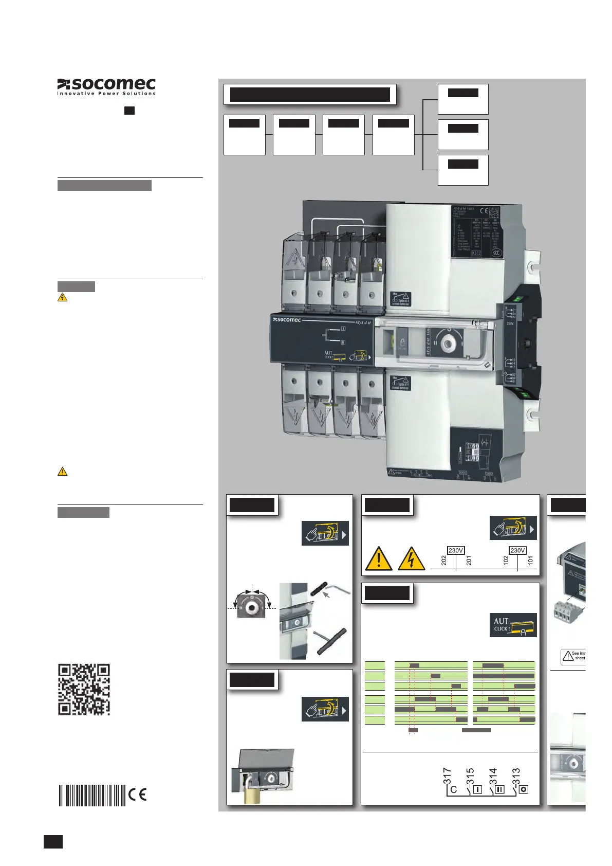
3.1. Quick Start ATy
quick start 40-160A (2P)
EN
ATyS d M
Remotely operated
Transfer Switching Equipment
Preliminary operations
Check the following upon delivery and after removal of the
packaging:
n Packaging and contents are in good condition.
n The product reference corresponds to the order.
n Contents should include:
Qty 1 x ATyS M
Qty 1 x Emergency handle extension rod
Qty 1 x Set of terminals
Quick Start instruction sheet
Warning
Risk of electrocution, burns or injury to persons and /
or damage to equipment.
This Quick Start is intended for personnel trained in the
installation and commissioning of this product. For further
details refer to the product instruction manual available on
the SOCOMEC website.
n This product must always be installed and commissioned
by qualified and approved personnel.
n Maintenance and servicing operations should be
performed by trained and authorised personnel.
n Do not handle any control or power cables connected to
the product when voltage may be, or may become present
on the product, directly through the mains or indirectly
through external circuits.
n Always use an appropriate voltage detection device to
confirm the absence of voltage.
n Ensure that no metal objects are allowed to fall in the
cabinet (risk of electrical arcing).
Failure to observe good enginering practises as well as to
follow these safety instructions may expose the user and
others to serious injury or death.
Risk of damaging the device
n In case the product is dropped or damaged in any way it
is recommended to replace the complete product.
Accessories
n Bridging bars and 125A or 160A.
n Voltage sensine and power supply TAP.
n Terminal shrouds.
n Additionnal aux contact block.
n Plastic enclosure.
n Dual Power Supply (DPS).
n Power Connection Terminals.
n ATS Control relay ATyS C30 + D10 or D20.
n ATS control relay ATyS C20.
n ATS control relay ATyS C40.
Printing informations: 1 color Black. White paper 90g/m
2
.
Printing size: 420x297. Final size 210x297. This page visible first.
A separate sheet for each language.
Non contractual document.
Subject to change without notice.
STEP 1
Cabinet / Back
Plate Installation
STEP 3
CONTROL /
AUX POWER
terminal
connections
STEP 2
Connecting the
POWER section
STEP 4
CHECK
Installation and Commissioning
STEP 5A
Automatic Operation
STEP 5C
Padlocking
STEP 5B
Emergency Manual
Operation
www.socomec.com
www.socomec.com/en/atys-d-m
To download, brochures, catalogues and technical manuals.
the ATySM as follows before
movementonthe DINrail.
!
Voltage taps provide 2x ≤ 1.5mm
STEP 4
STEP 5A
Check
Automatic operation
Ensure that the product is in Manual Mode (front cover open).
Whilst in manual mode, check the wiring and
ifok power up theproduct.
Close the front cover as shown to put the product
into automatic mode. The product is now ready to
receive order inputs based on the following logic.
Note: Excludes position switching delays.
For contactor logic bridge
contact 313 with 317.
To operate: close the
contact corresponding to
the desired position.
Auxiliary contacts:
Fitting of the 2nd
To fit an AC, the s
NC changeover contact for each position (I-0-II).
Imp. ≥60ms maintened
order I
position I
order 0
position 0
order II
position II
Contactor logicImpulse logic
STEP 5B
Manual operation
•
Open the front cover as
shown to put into manual
mode.
•
Use the handle situated in
the front panel under the cover to operate the
transfer switch.
•
Check the changeover switch position on the
indicator before operating.
To simplify operation
use the handle with the
extension provided.
(Max 8 Nm)
90º 90º
Extension
STEP 5C
Padlocking mode
1x 4-8 mm
•
In order to padlock put the
product in manual mode.
•
Pull the locking mecha-
nism and insert a padlock
as shown.
• As standard padlocking in the 0 position.
Configurable to I-0-II (see step 1).
CORPORATE HQ CONTACT:
SOCOMEC SAS, 1-4 RUE DE WESTHOUSE, 67235 BENFELD, FRANCE

 Loading...


