2
1
Dual auxiliary supply:
Uc 208-277V~ +/-20% 50/60Hz
Power comsumption: 22VA
See instruction sheet
ATS CONTROLLER
To D10
To D20
64B 63B
64B 63B
417 416 415 414 413
207 208 209 210
417 416 415 414 413
207 208 209 210
7172 74
7172 74
ATyS t
Dual auxiliary supply:
Uc 208-277V~ +/-20% 50/60Hz
Power comsumption: 22VA
See instruction sheet
ATS CONTROLLER
ATyS p
Dual auxiliary supply:
Uc 208-277V~ +/-20% 50/60Hz
Power comsumption: 22VA
See instruction sheet
ATS CONTROLLER
ATyS g
Dual auxiliary supply:
Uc 208-277V~ +/-20% 50/60Hz
Power comsumption: 22VA
See instruction sheet
ATS CONTROLLER
To D10
To D20
64B 63B
64B 63B
417 416 415 414 413
207 208 209 210
417 416 415 414 413
207 208 209 210
7172 74
7172 74
ATyS t
Dual auxiliary supply:
Uc 208-277V~ +/-20% 50/60Hz
Power comsumption: 22VA
See instruction sheet
ATS CONTROLLER
ATyS p
Dual auxiliary supply:
Uc 208-277V~ +/-20% 50/60Hz
Power comsumption: 22VA
See instruction sheet
ATS CONTROLLER
ATyS g
5
6
4
3
2 1
2
7
104 103
312313 314315 316317 63A64A 24 14 04 13
8 9
10
RJ
102 101
105106
414 413415416417
64B 63B
72
201
71
202
205 206204203
210209208207
74
15
14
13
12
11
1
F1
F2
19
20
16
17
18
I/1-2 I/3-4 I/5-6 I/7-8
II/1-2 II/3-4 II/5-6 II/7-8
Optional:
Fus. 4A
type gG
Optional:
Fus. 4A
type gG
23
3
Opt. 3
2
Opt. 2
1
Opt. 1
4
Opt. 4
21
21
22
22
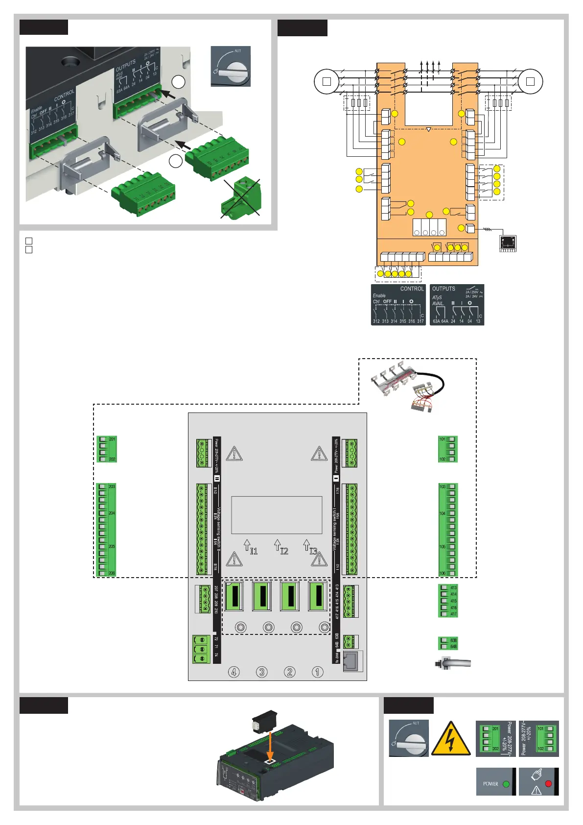
Ensure that the product is in Manual Mode.
CONTROL / COMMAND Terminals
1
preferred source
2
alternate source
1. Position 0 order
2. Position 1 order
3. Position 2 order
4. Zero position priority order
5. Remote Control Enable (Priority over Auto)
6. Product Available output (Motor)
7. Position II aux contact
8. Position I aux contact
9. Position 0 aux contact
10. O/P to ATyS D10 remote display
11. Product Available output (ATS)
12. I/P Inhibition of the ATS controls
13. I/P Manual retransfer
14. S2 Stability Time Bypass: 2AT
15. M-G: Priority to TON / M-M: Priority
enable/disable
16. TEST OFF LOAD Signal : TOF
17. M-G: Test On Load Input (TON) /M-M:
Priority source selection
18. Not used
19. Contact “Start/Stop Genset” : if S1 is not
available the NC contact (71-72) is close
20. Contact “Start/Stop Genset” : if S1 is not
available the NO contact (71-74) is open
21. Voltage Sensing Inputs
22. Power Supply Inputs
23. Option module slots 1 to 4
Power Supply, Sensing and Control wiring (ATS Controller)
Communication between the software and the ATyS g may be done
through the Modbus RTU module which is available as an option. The
MODBUS module is to be installed in one of the slots provided in the
ATyS g ATS control unit. Easy Config may be installed on a PC
connected through MODBUS module for a direct ATyS configuration,
either isolated with possibility to create a specific configuration for a
later upload and use in ATyS.
Note: The ATyS g may accept 1 additional MODBUS communication
module. Refer to the ATyS g accessory section for details.
Modbus RS485 Ref. 48250092 Factory settings:
Address: 10
Baud Rate: 38400
Stop Bit: 1
Parity: None
Optional Module
Slots for optional module
See STEP 4B
ATS Module
Control Inputs
(Fixed)
ATS Module
Control Inputs
(Fixed)
ATS Module
Output Contact
(Product available)
Genset Start/Stop
Signal
Remote interface
RJ45 - to ATyS D10
ATS Voltage
Sensing Input
Source supply I
S I - Phase / Neutral
S I - Phase
S I - Phase
575 VAC (ph-ph) max
S I - Neutral / Phase
332 VAC (ph-n) max
ATS Power Supply
InputI
Power supply I - L/N
Power supply I - N/L
208-277VAC ±20%:
50/60 Hz
Recommanded to use SOCOMEC
Voltage Sensing Kit
(refer to ATyS g
accessories
for details)
ATS Voltage Sensing
Input
Source supply II
S II - Phase / Neutral
S II - Phase
S II - Phase
575 VAC (ph-ph) max
S II - Neutral / Phase
332 VAC (ph-n) max
ATS Power Supply
InputII
Power supply II - L/N
Power supply II - N/L
208-277VAC ±20%:
50/60 Hz
Whilst in manual mode, check the wiring and if ok power up the
product.
LED “Power” Green: ON
LED Manuel/Fault Red: ON
Example: Control wiring for a 400 VAC application having a 3 phase and neutral supply.
STEP 3
STEP 4B
STEP 4A
STEP 5
Check
ATyS Voltage
Sensing and
Power supply
Kit excludes the
need for fuses
F1 & F2.
Connect the product with a cable of section of 1,5 to 2,5 mm
2
.
Screw M3 - Tightening torque:
min.: 0.5 Nm - max.: 0.6 Nm / min.: 4.43 lbin - max.: 5.31 lbin
ATyS D10
Remote
Display Unit

 Loading...


