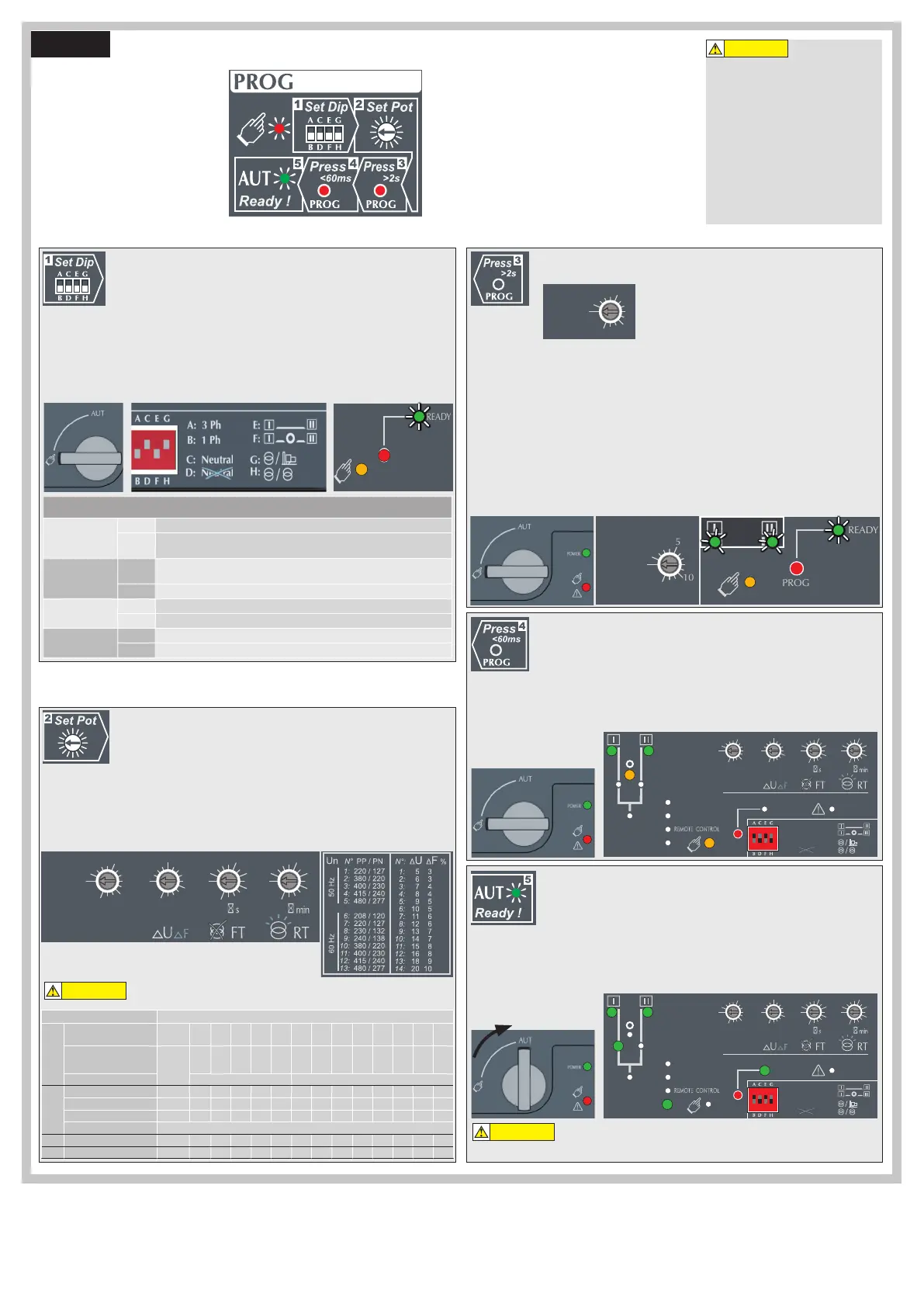
Programming the ATyS g
Note: Ensure that the ATyS g is in
“Manual Mode”, powered and with at
least one network supply available.
The ATyS g is programmed after wiring
verification tests through the front of
the ATS Controller in 5 steps:
As a safety measure the READY LED will
flash when any of the settings shown on the
controller are different to those that are saved.
To return to the steady READY LED revert to
the saved setting values or save the displayed
value by pressing the PROG OK button briefly.
(This is intended as a visual alarm in case one
has changed the configuration settings but has
not yet saved the new values in the product).
For added security the ATyS g may be
equipped with a sealable cover so as to limit
the access to configuration settings. Refer
to the product accessory section for details.
WARNING
STEP 6
WARNING
Dip Switch Setting Options Auto Configuration of Mains Voltage and Frequency
Depending on the state of the ATyS g the ATS automation may change the
switch position as soon as the mode selector is switched to AUT. This is a
normal operation.
POWER
AUT
Ø 4 ... 8mm
PROG
OK
AUT
READY
TEST ON LOAD
TEST OFF LOAD
ATyS g
Un
Auto Conf
5
1
10
14
5
1
10
13
0
1
5
10
20
60
0
1
5
10
20
60
G:
H:
E:
F:
REMOTE CONTROL
A: 3 Ph
B: 1 Ph
C: Neutral
D: Neutral
ATyS
Un
N°
PP / PN
1: 220 / 127
2: 380 / 220
3: 400 / 230
4: 415 / 240
5: 480 / 277
6: 208 / 120
7: 220 / 127
8: 230 / 132
9: 240 / 138
10: 380 / 220
11: 400 / 230
12: 415 / 240
13: 480 / 277
5
6
7
8
9
10
11
12
13
14
15
16
18
20
1:
2:
3:
4:
5:
6:
7:
8:
9:
10:
11:
12:
13:
14:
3
3
4
4
5
5
6
6
7
7
8
8
9
10
N°: Δ
U ΔF %
XXX
50 Hz60 Hz
XXXXXXXX
Motorised Changeover Switch
1600A Ref : 95054160
PROG
OK
AUT
READY
TEST ON LOAD
TEST OFF LOAD
Un
Auto Conf
1
10
14
1
10
13
0
1
10
20
60
0
1
10
20
60
G:
H:
E:
F:
REMOTE CONTROL
A: 3 Ph
B: 1 Ph
C: Neutral
D: Neutral
ATyS
Un N° PP / PN
1: 220 / 127
2: 380 / 220
3: 400 / 230
4: 415 / 240
5: 480 / 277
6: 208 / 120
7: 220 / 127
8: 230 / 132
9: 240 / 138
10: 380 / 220
11: 400 / 230
12: 415 / 240
13: 480 / 277
5
6
7
8
9
10
11
12
13
14
15
16
18
20
1:
2:
3:
4:
5:
6:
7:
8:
9:
10:
11:
12:
13:
14:
3
3
4
4
5
5
6
6
7
7
8
8
9
10
N°: Δ
U ΔF %
XXX
50 Hz60 Hz
XXXXXXXX
Motorised Changeover Switch
1600A Ref : 95054160
PROG
OK
ON LOAD
TEST OFF LOAD
ATyS g
Un
Auto Conf
5
1
10
14
5
1
10
13
0
1
5
10
20
60
0
1
5
10
20
60
G:
H:
E:
F:
REMOTE CONTROL
A: 3 Ph
B: 1 Ph
C: Neutral
D: Neutral
ATyS
Un N° PP / PN
1: 220 / 127
2: 380 / 220
3: 400 / 230
4: 415 / 240
5: 480 / 277
6: 208 / 120
7: 220 / 127
8: 230 / 132
9: 240 / 138
10: 380 / 220
11: 400 / 230
12: 415 / 240
13: 480 / 277
5
6
7
8
9
10
11
12
13
14
15
16
18
20
1:
2:
3:
4:
5:
6:
7:
8:
9:
10:
11:
12:
13:
14:
3
3
4
4
5
5
6
6
7
7
8
8
9
10
N°: Δ
U ΔF %
XXX
50 Hz60 Hz
XXXXXXXX
Motorised Changeover Switch
1600A Ref : 95054160
POWER
AUT
Ø 4 ... 8mm
PROG
OK
AUT
READY
TEST ON LOAD
TEST OFF LOAD
ATyS g
Un
Auto Conf
5
1
10
13
0
1
5
10
20
60
0
1
5
10
20
60
G:
H:
E:
F:
REMOTE CONTROL
A: 3 Ph
B: 1 Ph
C: Neutral
D: Neutral
ATyS
Un N° PP / PN
1: 220 / 127
2: 380 / 220
3: 400 / 230
4: 415 / 240
5: 480 / 277
6: 208 / 120
7: 220 / 127
8: 230 / 132
9: 240 / 138
10: 380 / 220
11: 400 / 230
12: 415 / 240
13: 480 / 277
5
6
7
8
9
10
11
12
13
14
15
16
18
20
1:
2:
3:
4:
5:
6:
7:
8:
9:
10:
11:
12:
13:
14:
3
3
4
4
5
5
6
6
7
7
8
8
9
10
N°: Δ
U ΔF %
XXX
50 Hz60 Hz
XXXXXXXX
Motorised Changeover Switch
1600A Ref : 95054160
POWER
AUT
Ø 4 ... 8mm
PROG
OK
AUT
READY
TEST ON LOAD
TEST OFF LOAD
ATyS g
Un
Auto Conf
1
10
13
0
1
5
10
20
60
0
1
5
10
20
60
G:
H:
E:
F:
REMOTE CONTROL
A: 3 Ph
B: 1 Ph
C: Neutral
D: Neutral
ATyS
Un N° PP / PN
1: 220 / 127
2: 380 / 220
3: 400 / 230
4: 415 / 240
5: 480 / 277
6: 208 / 120
7: 220 / 127
8: 230 / 132
9: 240 / 138
10: 380 / 220
11: 400 / 230
12: 415 / 240
13: 480 / 277
5
6
7
8
9
10
11
12
13
14
15
16
18
20
1:
2:
3:
4:
5:
6:
7:
8:
9:
10:
11:
12:
13:
14:
3
3
4
4
5
5
6
6
7
7
8
8
9
10
N°: Δ
U ΔF %
XXX
50 Hz60 Hz
XXXXXXXX
Motorised Changeover Switch
1600A Ref : 95054160
SET the 4 Dip Switches using a small screw driver. Possible variants vary from positions “A to
H” as described in the table below. For convenience, the position functions are also described
on the front of the ATS controller adjacent to the dip switches.
Note: The READY LED will flash green as soon as settings are changed and until the new
settings have been saved by pressing the PROG OK button momentarily.
Dip Switch Setting Options
Dipswitch 1
A / B
A Three Phase Network
B
Single Phase Network
(Attn : Dipswitch 2 is inactive in this position)
Dipswitch 2
C / D
C
Three Phase 4 wire Network (Including Neutral)
(Allows to detect a loss of neutral for unbalanced loads)
D Three Phase 3 wire Network (Without Neutral)
Dipswitch 3
E / F
E Load supply down time of 0 second (0DT = 0 sec)
F Load supply down time of 2 seconds (0DT = 2 sec)
Dipswitch 4
G / H
G Main - Generator Application
H Main - Main Application
WARNING
Whatever Pot 1 trimming, it is IMPERATIVE to set Pots 2 to 4.
POWER
AUT
Ø 4 ... 8mm
PROG
OK
AUT
READY
TEST ON LOAD
TEST OFF LOAD
ATyS g
Un
Auto Conf
5
1
10
14
5
1
10
13
0
1
5
60
0
1
5
10
20
60
G:
H:
E:
F:
REMOTE CONTROL
A: 3 Ph
B: 1 Ph
C: Neutral
D: Neutral
ATyS
Un N° PP / PN
1: 220 / 127
2: 380 / 220
3: 400 / 230
4: 415 / 240
5: 480 / 277
6: 208 / 120
7: 220 / 127
8: 230 / 132
9: 240 / 138
10: 380 / 220
11: 400 / 230
12: 415 / 240
13: 480 / 277
5
6
7
8
9
10
11
12
13
14
15
16
18
20
1:
2:
3:
4:
5:
6:
7:
8:
9:
10:
11:
12:
13:
14:
3
3
4
4
5
5
6
6
7
7
8
8
9
10
N°: Δ
U ΔF %
XXX
50 Hz60 Hz
XXXXXXXX
Motorised Changeover Switch
1600A Ref : 95054160
Potentiometer Setting Options
SET the 4 potentiometers using a small screw driver paying attention to the arrow indicating
the position. There are a total of 14 positions for which the specific settings are described in
the table below.
Note: The READY LED will flash green as soon as settings are changed and until the new
settings have been saved by pressing the PROG OK button momentarily.
Potentiometer Conguration
Un
Position
Auto
Conf
1 2 3 4 5 6 7 8 9 10 11 12 13
PP / PN
Mesured
220 /
127V
380 /
220V
400 /
230V
415 /
240V
480 /
277V
208 /
120V
220 /
127V
230 /
132V
240 /
138V
380 /
220V
400 /
230V
415 /
240V
480 /
277V
F
50Hz 60Hz
∆U/
∆F
Position 1
2 3 4 5 6 7 8 9 10 11 12 13 14
U threshold in % of Un 5%
6% 7% 8% 9% 10% 11% 12% 13% 14% 15% 16% 18% 20%
F threshold in % of Fn 3%
3% 4% 4% 5% 5% 6% 6% 7% 7% 8% 8% 9% 10%
Hysteresis 20% of ∆U/ ∆F settings
FT Source Failure Timer (s) 0
1 2 3 4 5 8 10 15 20 30 40 50 60
RT
Source Return Timer (min)
0
1 2 3 4 5 8 10 15 20 30 40 50 60
Saving the configured values
To SAVE the recorded setting configuration press the PROG OK button momentarily: <60ms.
Note: The flashing READY LED goes off once the values are saved in the ATS controller.
At least one of the source availability LED must be ON.
If the 1st potentiometer is not on “Auto Conf”,
go to STEP 4.
Putting the ATyS g into Auto Operation
After following Steps 1 to 4, and once ready to put the ATyS g into AUTO operation turn the
mode selector switch to Auto.
Note: When the product is powered and properly configured, after switching the product from
Manual Mode to Auto Mode the READY light should be a steady green light
The ATyS g includes an “Auto Configuration” feature to detect the mains voltage and frequency
nominal values, phase rotation and neutral position and saves them in the ATS controller.
Note: Before configuring the nominal values ensure that the product is properly wired, verified
and ready for commissioning. It is imperative that the network supply is available and that the
wiring to the ATyS g voltage sensing terminals 103 – 106 and 203 – 206 has been done. It is
preferable to use the ATyS sensing kit that may be provided as an accessory.
• Press and hold the Red “PROG OK” button for >2s to measure the mains voltage and
frequency.
Note: The source available LED will flash while the available network is being measured. The
READY LED will flash green as soon as settings are measured and until these settings have
been saved by pressing the PROG OK button a second time momentarily. (Refer to STEP 4).

 Loading...


