EN
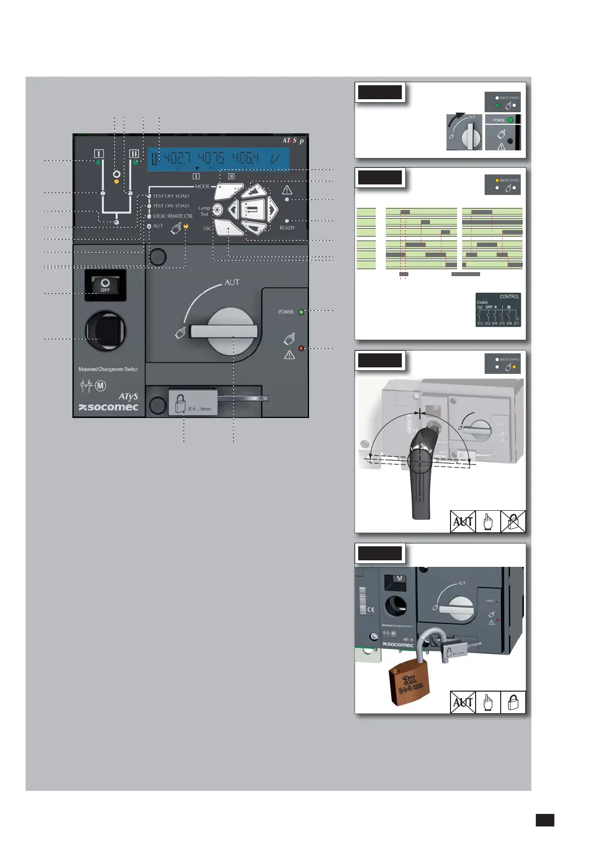
1. MANUAL Mode LED indication. (Yellow
steady light when in Manual Mode).
2. AUTO Mode LED indication Green steady
light when in Auto mode with no timers
running.
Green flashing light when in Auto with timers
running.
3. LOCAL / REMOTE CONTROL Mode LED
indication.
Yellow steady light when in Local / Remote
control mode.
Remote control mode is achieved with the
Auto/Manu selector switched to Auto and
terminals 312 closed with terminal 317.
Remote control orders are received through
closing 314 to 316 with 317.
REMOTE Control is also achievable through
connected to the product through Ethernet or
MODBUS. (Optional modules). Local Control
selectable and operable through the ATyS
p keypad.
4. TEST ON LOAD CONTROL Mode LED
indication. (Yellow steady light when in TON/
5. TEST OFF LOAD CONTROL Mode LED
indication. (Yellow steady light when in TOF/
EOF mode).
6. Load Supply On LED. (Green when the load
is supplied).
7. Switch 1 LED position indication. (Green
when in position 1).
8. Source supply I availability LED indication.
(Green when supply I voltage is within the
set limits).
9. Zero position LED indication. (Yellow when
in position 0).
10. Switch 2 LED position indication. (Green
when in position 2).
11. Source supply II availability LED indication.
(Green when supply II voltage is within the
set limits).
12. LCD Display Screen : (Status,
measurement, timers, counters, events,
faults, programming …. )
13. MODE key to shift between operation
modes.
14. Navigation Keys to browse through the
ATyS p menus without software.
15. FAULT LED indication. (Red steady light
in case of an ATS controller internal fault.
Switch the product from Auto to Manual
and back to Auto to reset a fault condition).
16. READY LED indication. (Green steady
light : Product is powered and in AUTO,
Watchdog OK, The Product is Available to
changeover).
17. Enter Key used to enter Prog Mode (Press
and hold for 5 seconds) and to validate the
settings programmed through the keypad.
18. ESC key used to escape from a specific
screen up to the main menu.
19. Lamp test key to check the LED’s and LCD
screen.
20. Green LED Indication: Power
21. Red LED Indication: Product Unavailable /
Manual Mode / Fault Condition
22. Auto / Manual mode selector switch
(Key version available as an option)
23. Padlocking facility
(Up to 3 padlocks of dia. 4 - 8mm)
24. Emergency manual operation shaft location
(Accessible only in manual mode)
25. Switch position indication window:
I (On switch I) O (Off) II (On switch II).
2223
24
25
8
7
2
3
4
5
1
6
15
20
21
17
18
13
14
19
1110 129
16
Ensure that the emergency handle is
not inserted in the product and turn
the mode selector to the AUT position.
LED “Power” Green: ON
LED Manuel/Default: OFF
STEP 7A
AUT Mode
STEP 7B
AUT Mode
To enable control, close contact 312 with 317.
For contactor logic bridge contact 316 with 317.
To operate: close the contact corresponding to
the desired position.
To force the product to 0 position “OFF” bridge
contact 313 with 317.
maintened
order I
position I
order 0
position 0
order II
position II
Contactor logicImpulse logic
STEP 7D
Padlocking Mode
(as standard : in position O)
STEP 7C
Manual Mode
90°
90°
III
0
AUT
AUT
REMOTE CONTROL
AUT
REMOTE CONTROL
AUT
REMOTE CONTROL

 Loading...


