SR5 MANUAL
4- ASSEMBLY OF THE STEERING COLUMN AND STEERING WHEEL.
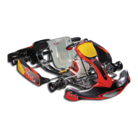
THE SET CONSISTS IN:
6
4
2
5
3
1
PIC 1
¾ One plastic steering column support (1).
¾ One steering wheel support (2).
¾ Two nassau panel supports
(3).
¾ One steering column (4).
¾ One steering column support (5).
¾ Two steering tie rods + ball joints (6).
¾ Raise the set as in picture 1.
2
1
3
PIC 2
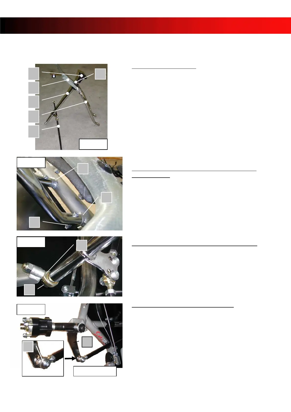
4.1 ASSEMBLY OF THE STEERING COLUMN
SUPPORT (PIC 2)
¾ Place the steering column support on the two pins
canons (1) and (2).
¾ Put the CHC M6x30 (3) screws + nylstop M6 bolts
as indicated in picture 2.
¾ Tighten.
4
5
PIC 3
4.2 ASSEMBLY OF THE STEERING COLUMN
(PIC 3)
¾ Insert the threaded end of the steering column in
the ball joint (4).
¾ Place the bolt (5).
¾ Tighten.
4.3 ASSEMBLY OF THE TIE-RODS
(PIC 4)
6
7
PIC 4
Inner hole
After cutting the tie-wrap maintaining the stub axles:
¾ Place the ball joints (6) above the stub axle arm
(7).
¾ Insert the BHC M8x30 screw in the outer hole of
the stub axle arm.
¾ Place the washer on top of the ball joint and insert
the screw.
¾ Place the M8 bolt and tighten.
- 7 -