HYD 5-20KTL-3PH User manual
Copyright © Shenzhen SOFARSOLAR Co., Ltd。
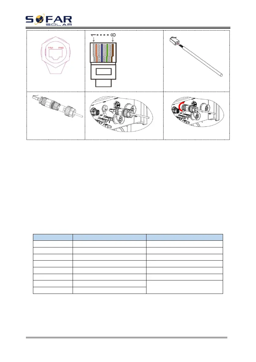
1.White and orange
2.Orange
3.White and green
4.Blue
5.White and blue
6.Green
7.White and brown
8.Brown
②
Procedure:
Step 1 Press the wire terminals in color sequence.
Step 2 Route Cable terminal through the cable gland, Insert the communication
cable into the RJ45 connector.
The logic interface pin definitions and circuit connections are as follows:
Logic interface pin are defined according to different standard requirements
(a)Logic interface for AS/NZS 4777.2:2015, also known as inverter demand
response modes (DRMs).
The inverter will detect and initiate a response to all supported demand
response commands within 2 s. The inverter will continue to respond while the
mode remains asserted.
Table 4-5 Function description of the DRMs terminal
(b)Logic interface for VDE-AR-N 4105:2018-11, is in order to control
and/or limit the inverter’s output power.
The inverter can be connected to a RRCR (Radio Ripple Control Receiver) in
order to dynamically limit the output power of all the inverters in the installation.
Fig.4-7 Inverter – RRCR Connection