HYD 5-20KTL-3PH User manual
Copyright © Shenzhen SOFARSOLAR Co., Ltd。
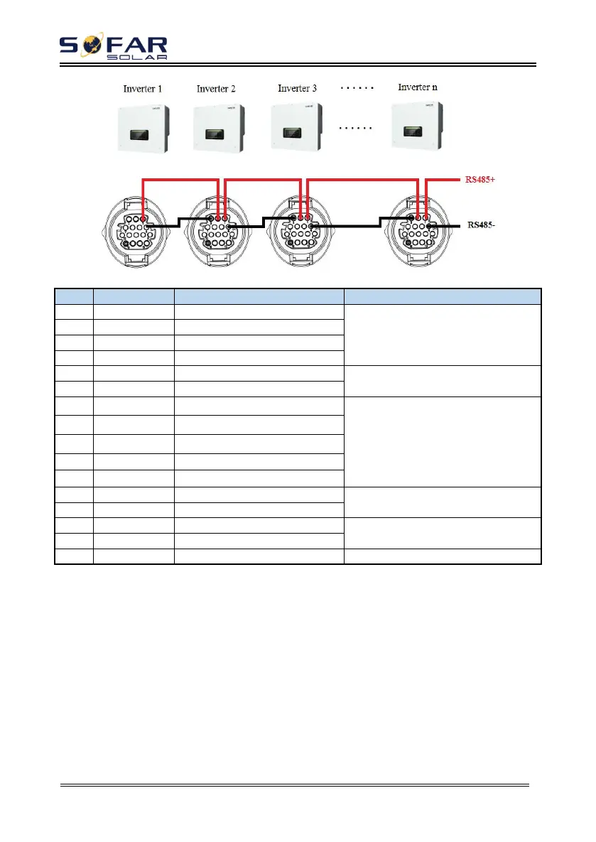
Table 4-10 Interface description
RS485 differential signal +
Wired monitoring or inverter
cascade monitoring
RS485 differential signal +
RS485 differential signal –
RS485 differential signal –
RS485 differential signal +
Communicate with electricity
meters
RS485 differential signal -
Communication with lithium
battery BMS, the inverter CAN be
adaptive to lithium battery BMS to
provide CAN communication and
RS485 communication
RS485 differential signal +
RS485 differential signal -
Sampling battery temperature
Battery temperature sampling
Providing electrical switching
function
PIN5 and PIN6 are used for meter communication, the electricity meter is
shown in the fig.4-11①, PIN5 and PIN6 correspond to 24,25 respectively on the
electricity meter, as shown in fig.4-11
③.
The connection mode is shown in fig.4-11②. The 2,5,8 and 10 on the
electricity meter are connected to voltage signals A,B,C and N respectively.
And the current needs to be connected through the current transformer,1,3
correspond to the A-phase current transformer, 4,6 correspond to the B-phase, 7,9
correspond to the C-phase.
NOTE:The direction of the current transformer is shown in fig.4-11
④.
Fig.4-11 Meter