24 | WORKING WITH CONSOLE1
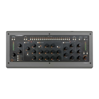
The Input Section
In the Input Section of Console1, you’ll nd the
Input Gain knob. is adjusts the gain (volume
level) of the incoming sound. Its setting is displayed
numerically in the On-Screen Display. e input
gain meter displays the signal level post the Input
Gain knob—meaning adjustments to the Input
Gain setting will be reected in what level the
meter displays. In most cases, it is a good idea to
adjust the level so the signal’s peaks reach between
–12 and –6 dBFS.
High and Low Cut
e sweepable High Cut and Low Cut lters can
be used to narrow down the frequency span of the
signal. e lters’ cuto frequencies will be reected
numerically in the input section of the On-Screen
Display, and will aect the graphical equalizer curve.
Many mix engineers have taken the habit of using
Low Cut on most sound sources, except for bass
instruments and kick drums, to remove unwanted
low frequency rumble from the signal. High Cut is
useful for re-
moving un-
wanted hiss
from signals
that do not
have very
much high
frequency
content
anyways.
It is of course
entirely pos-
sible to use
the High
and Low
Cut lters
in a more creative manner—to not just clean up
unwanted rumble and hiss, but to actually aect
the sound source to better t in the mix. e slope
and character of the High
Cut and Low Cut lters are
determined by what channel
strip has been loaded into
the track. So in the case of
the included SSL SL4000E,
the High and Low Cut
lters are modeled o that
console. We have however
extended their working range
quite radically.
With the Low Cut knob
turned fully counterclock-
wise, the lter is entirely by-
passed. In a similar manner,
the same applies to the High
Cut lter when its knob is
turned fully clockwise.
Filters to Compressor
By pressing the Filters to
Compressor button, the
High and Low Cut lters
will no longer aect the
sound source directly, but
instead the sidechain signal
of the compressor. Read more
about this in “Filtering the
Compressor Sidechain” on
page 31.
Phase Invert
Phase Invert inverts the phase (polarity) of the
signal, so that all negative parts of the signal’s wave-
form become positive and vice versa. is is useful
to correct issues where for example a microphone