9
Instruction Manual INOXA SERIES
GB
English
GB
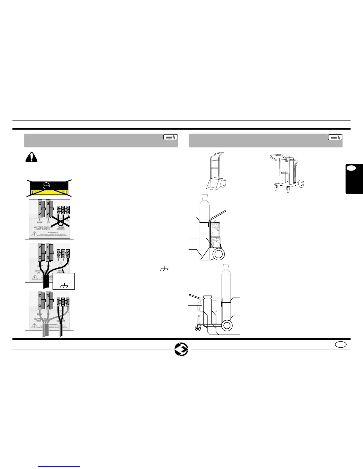
8.4 COOLER UNIT
CONNECTION (OPTIONAL)
Warning! Before the installation, it is necessary to make
sure the generator is not connected to the net.
NOTE: the following numbers refer to Fig. 2 to Page 5.
1. Remove the adhesive from the panel
door (22).
2. Open the two wholes on the panel
door and fix the cable holders, given
with the package, to the cooling unit.
3. Open the panel door (22) by
unscrewing the screws (22A).
4. Pass the cable (26) and (27) into the
cable holder.
5. Remove the jumper from the “FLOW
SWITCH” clamps.
6. Connect the cable (27) AC 400V, to
the clamps “400V”, “0V” and “ “.
NOTE WELL: the earth wire (Yellow
Green) must be connected to the
right clamp.
7. Connect the cable (26) (flowmeter
water signal) to the “FLOW SWITCH”
clamps.
8. Fix the cable holder and close the
panel door (22).
YELLOW
GREEN
8.5 INSTALLATION ON 2/4 WHEELS TROLLEY
(OPTIONAL)
NOTE: for the assembling of the Trolley
refer to the instructions inside the packa-
ges of the Trolley.
1. Place the MACHINE and the
COOLER UNIT on the designated
compartment (30-31).
2. Fix the MACHINE and the COOLER
UNIT with the jack belt (28) on
the 2 wheels TROLLEY, with the
screws (33) on the 4 wheels Trolley.
3. Place the gas cylinder on the designa-
ted compartment (29).
4. Fix the GAS cylinder with the
chain (32).
30
29
31
32
33
32
28
29
30-31
TROLLEY 08
2 WHEELS
TROLLEY 08
4 WHEELS