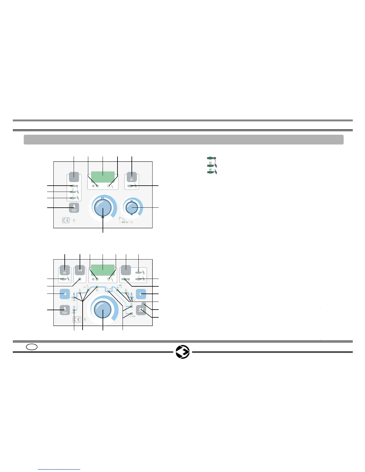
POS. 1 = Auswahltaster für die Betriebsarten:
POS. 1A = ELEKTRODE __________________________
POS. 1B = WIG 2 Takt-funktion ____________________
POS. 1C = WIG 4 Takt-funktion ____________________
POS. 2 = Netzlampe
POS. 3 = Display zur Anzeige des Schweißstroms SET und
REAL, Zeit der Abfallrampe (bei HFP-Serien zeigt es
auch den gewählten Parameter an)
POS. 4 = Störungslampe ____________________________
POS. 5 = Schalter HF ON/OFF _______________________
POS. 5A = LED HF ON / OFF
POS. 6 = Regler für Absenkzeit DOWN SLOPE __________
POS. 7 = Schweißstromregler
(bei HFP-Serien zeigt es auch den gewählten Parameter an)
POS. 8 = Gas-Test Drucktaste _____________________
POS. 9 = Druckknopf zur Wahl und Speicherung JOB _____
POS. 9A = LED "gewählte JOB"
POS. 10 = Druckknöpfe zur Wahl der Parameter 11 und 14
POS. 11 = LED gewählter Parameter:
(A) VORGAS-Zeit _________________________
(B) ANFANGSSTROM I1 ___________________
(C) STEIGUNGSRAMPE ____________________
(D) SCHWEIßSTROM I2
(E) ABHANGSRAMPE ______________________
(F) ENDSTROM I3 _________________________
(G) POSTGAS-Zeit _________________________
POS. 12 =
Druckknopf zur Wahl der Modalität KREISFREQUENZ
POS. 12A = LED KREISFREQUENZ ON / OFF
POS. 13 = LED gewählte Kreisfrequenzparameter
POS. 14 = LED gewählte Modalität TIMER ________________
Bedienungsanleitungen INOXA SERIES
4
D
6. BESCHREIBUNG DER BEDIENELEMENTE INOXA 250 HF / INOXA 360 HF / INOXA 250 HFP / INOXA 360 HFP
Abb. 1
1
2345
7
Seite 7
Seite 10
Seite 10
Seite 18
Seite 11
Seite 13
Seite 8-16
Seite 15
Seite 14
Seite 14
Seite 13
Seite 13
Seite 14
Seite 14
Seite 14
Seite 13
5
234
14
7
5A
6
1A
1B
1C
8
9
1 1B
1C
1A
10
5A
10
9A
12A
8
13
11
11
HF series
HFP series
12
A
B
C
D
E
F
G
H
I
L