SOLAR ELECTRONICS COMPANY
calculated using Ohms law. After verifying the waveform and current, a Spike Receptor Probe, Type
7541-1 was identified with a lower cutoff frequency (1 kHz). This receptor probe was then used to re-
measure and verify that the current waveform was the same as the voltage waveform measured across
the 0.1Ω resistor.
Although the resulting short circuit current waveform was better than originally measured, the coupling
device or injection probe was still saturated and limited at the low frequency end of the spectrum. To
further improve the fidelity of the current waveform, the level of the pulse generator had to be reduced
and the injection probe's low frequency performance increased. This meant either adding more primary
turns and/or magnetic core material to increase the level of saturation, lower the cutoff frequency, and
increase the injection probe's impedance, or reducing the pulse amplitude and driving the injection probe
from a lower source impedance. In an effort to use existing equipment, the second proposed solution was
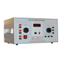
selected. This was accomplished by connecting the 70 μS output of the Model 9354-2 Transient Pulse
Generator into the primary of a Type 6220-4 Audio Isolation Transformer (2:1 step down) and connecting
the secondary into Port 2 of the Type 9335-2 Multi-port Coupling Device (2:1 step down). However, it
should be noted that this test configuration is limited to a short circuit current of about 120 Ipk with a
pulse width of 70 us, and a matched circuit current of 30 Ipk with a pulse width of 35 μS and a voltage
output of 60 Vpk.