EasyManua.ls Logo

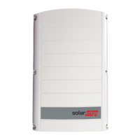
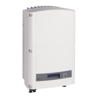
SolarEdge SE8k User Manual

SolarEdge SE8k
114 pages
To Next Page IconTo Next Page
Page #1 background imageLoading...
Page #1 background image
Installation Guide
SolarEdge System
Installation Guide
For Europe and APAC
Version 4.1

Table of Contents

Questions and Answers:

SolarEdge SE8k Specifications

General IconGeneral
AC Output Power8000 W
CEC Weighted Efficiency97.5%
CoolingNatural Convection
Protection RatingIP65
Rated AC Power8000 W
Warranty12 years
Weight26 kg
Operating Temperature Range-25°C to 60°C
AC Voltage208/240 V

Summary

Disclaimers

Important Notice

General legal notices and copyright information for the document.

Emission Compliance

Support and Contact Information

Contact Details and Support Info

Contact details and required information for technical support.

Revision History

Version Updates

Details of changes and updates made in different versions of the guide.

Handling and Safety Instructions

Safety Symbols Information

Explanation of safety symbols used throughout the manual.

Important Safety Instructions

Critical Safety Precautions

Critical safety warnings and precautions for installation and operation.

Chapter 1: Introducing the SolarEdge Power Harvesting System

System Components Overview

Overview of Power Optimizer, Inverter, and Monitoring Platform.

Installation Procedure and Equipment

Steps for site setup and recommended tools.

Inverter Transport and Storage

Guidelines for safe transport and storage of the inverter.

Chapter 2: Installing the Power Optimizers

Safety and Installation Guidelines

Safety notes and general guidelines for power optimizer installation.

Step 1: Mounting the Power Optimizers

Step 2: Connecting a PV Module to a Power Optimizer

Step 3: Connecting Power Optimizers in Strings

Step 4: Verifying Proper Power Optimizer Connection

Chapter 3: Installing the Inverter

Inverter Package Contents

List of items included in the inverter package.

Identifying the Inverter

How to locate serial number and electrical ratings on the inverter.

Inverter Interfaces

Description of the inverter's connectors and components.

Mounting the Inverter

Chapter 4: Connecting the AC and the Strings to the Inverter

Grid Connection Guidelines

Guidelines for connecting the inverter to the AC grid.

Connecting the AC Grid to the Inverter

Connecting the Strings to the Inverter

Selecting a Residual Current Device (RCD)

Chapter 5: Commissioning the Installation

Step 1: Activating the System

Procedures to activate the inverter and system.

Step 2: Pairing Power Optimizers to the Inverter

Step 3: Verifying Proper Activation

Step 4: Reporting and Monitoring Installation Data

The Monitoring Platform

Logical Layout

Describes the schematic layout of system components and connectivity.

Physical Layout

Describes the visual placement of modules on a virtual site map.

Creating Logical and Physical Layout using Installation Information

Designer

Mapper Application

Using a Paper Template

Chapter 6: User Interface

LCD User Buttons

Explanation of the four buttons used to control the LCD menu.

Operational Mode

Setup Mode

Error Messages

Inverter Configuration – Setup Mode

Configuring the Inverter Using the Internal LCD User Buttons

Steps to configure the inverter using the internal LCD buttons.

Configuring the Inverter Using the LCD Light Button

Configuration Menu Options

Country and Grid

Configuring country and grid settings via the internal buttons.

Language

Setting the display language for the LCD panel.

Communication

Options for setting up communication with the monitoring platform.

Information Display Options

Versions

Displays inverter firmware versions (ID, DSP, CPU).

Error Log

Displays the last five recorded errors.

Warning Log

Displays the last five recorded warnings.

Hardware IDs

Displays hardware serial numbers of connected devices.

Status Screens - Operational Mode

Initial Status

Displays initial status of the inverter.

Main Inverter Status

Displays main operational status including frequency and temperature.

Energy Meter Status

Displays total energy produced.

Telemetry Status

Displays last received telemetry data from power optimizers.

ID Status

Displays inverter software version and configured country.

Server Communication Status

Shows the status of communication with the SolarEdge server.

IP Status

Displays Ethernet configuration.

ZigBee Status

Displays ZigBee configuration details.

Wi-Fi Status

Displays Wi-Fi configuration details.

GSM Status

Displays status for GSM/CDMA plug-in communication.

Communication Ports Status

Shows status for RS485, ZigBee, and other communication ports.

Smart Energy Management Status

Displays energy details when Smart Energy Management is enabled.

Fan Status

Provides information about the status of internal and external fans.

Power Control Status

Displays status for power control features.

Chapter 7: Setting Up Communication

Communication Options

Overview of supported communication types.

RS485

Wi-Fi

Cellular (GSM, CDMA)

ZigBee

Communication Connectors

Removing the Inverter Cover

Creating an Ethernet (LAN) Connection

Creating an RS485 Bus Connection

Verifying the Connection

Appendix A: Errors and Troubleshooting

Troubleshooting Communication

Guides to troubleshoot communication issues, especially Ethernet.

Power Optimizer Troubleshooting

Appendix B: Mechanical Specifications

Appendix C: Connecting the AC and DC Strings to the DC Safety Unit

Connecting the AC Grid to the Inverter

Steps for connecting the AC grid via the DC Safety Unit.

Connecting the Strings to the DC Safety Unit

How to connect DC strings to the DC Safety Unit.

Appendix D: SafeDC™

Appendix E: External Fan Maintenance and Replacement

Fan Maintenance

Procedures for cleaning and checking the inverter fans.

External Fan Replacement

Steps for replacing an external fan in the inverter.

Appendix F: Replacing and Adding System Components

Replacing an Inverter

Procedures for replacing the inverter unit.

Replacing the DC Safety Unit

Procedures for replacing the DC Safety Unit.

Adding, Removing, or Replacing Power Optimizers

Appendix G: Determining the Circuit Breaker Size

Introduction

Importance of circuit breakers for inverter protection.

Using Transformers in Commercial Three Phase Inverter Installations

Optional use of transformers in commercial installations.

Determining the Size of an Inverter Circuit Breaker

Technical Specifications - Single Phase Inverters (Europe & APAC)

Technical Specifications - Three Phase Inverters (Europe & APAC)

SE4K - SE12.5K

Specifications for SE4K to SE12.5K three-phase inverters.

SE15K - SE33.3K

Specifications for SE15K to SE33.3K three-phase inverters.

Contact Information

Related product manuals