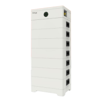
5. Equipment Installation 5. Equipment Installation
Step 6. Repeat the Step 5 until BMS has been put into the cabinet. The figure after
finishing installation is as follows.
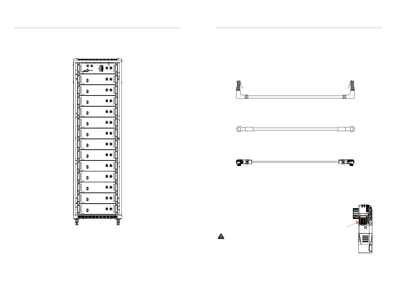
■ Wiring
After installation, connect a battery module to another battery (or BMS), and BMS
to inverter.
• Battery module to battery module (or BMS)
Communication cable (1 pc), power cable (1 pc) and ground wire (1 pc) are
provided in our packing list.
Power cable: there are two terminals with the same function at both ends; a power
cable in the packing list of battery module, one end connects to B+ of a battery
module, and the other connects to B- of the neighboring battery module (or B- of
BMS). A power cable in the packing list of BMS, one end connects B+ of BMS and
the other connects B- of a battery module at the bottom of the rack.
Ground wire: there are two terminals at both ends; one connects to a grounding
point of a battery module; and the other connects to grounding point of the
neighboring battery module or BMS.
Communication cable: there are two registered jacks at both ends; one connects to
Com-A of a battery module, and the other connects to Com-B of the neighboring
battery module (or COMM of BMS).
38
39
Caution!
Press and hold the “Lock Button” while unplugging the
power cable. Otherwise, it cannot be pulled out.
Lock Button
 Loading...