Grid
EPS(Off-grid)
L
₂=
12
mm
L
2
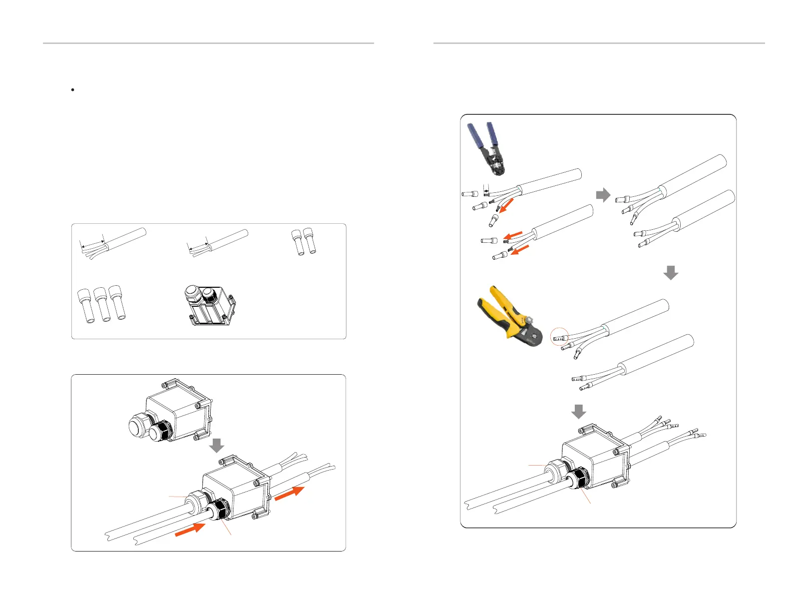
Diagonal plier
Crimping Tool
Electrical Connection
Electrical Connection
Grid
EPS(Off-grid)
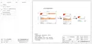
6 mm Euro Terminal*2
Waterproof shield
Grid(Triple Core Cable)
8 mm *3
Ø Grid and EPS(Off-grid) connection steps
EPS(Off-grid)(Double Core
Cable) 6 mm *2
Euro Terminal 8 mm *3
Connection requirements
44
45
Step 3. Remove the 12 mm insulation layer at the end of the wire. Insert
the European-style terminals respectively, and make sure that the
stripped ends are inserted into the European-style terminal, and finally
use crimping pliers to press tightly.
Notice: Check the grid voltage and compare the voltage range
(see technical data).
Disconnect the circuit board from all power sources to prevent electric
shock.
The Grid and the EPS(Off-grid) ports of M series inverter have been
connected, for specific installation details, please refer to the X1-Matebox
Quick Installation Guide. And the D series needs to be wired according to
the following steps.
Step 1. Prepare a Grid cable (three-core wire) and an EPS(Off-grid) cable
(two-core wire), and then find the European terminal and waterproof shield
in the accessory bag.
Step 2: The Grid and EPS(Off-grid) cables go through the corresponding
Grid and EPS(Off-grid) ports of the waterproof shield.
L
1
L
1
L =55
~
60 mm
1
L
=55
~
60 mm
1

 Loading...