Setting
Setting
Modbus
Baud Rate:
115200
Modbus
Address:
1
10) External ATS
Mode Comment
Off
Over-Excited PF value
Under-Excited PF value
Curve
Upper limit
Lower limit
Power Upper
Power Lower
PFLockInPoint ( CEI 0-21 only)
PFLockOutPoint ( CEI 0-21 only)
-
Fixed Q Power Q Power
Q( u )
VoltRATIO 1
VoltRATIO 4
QURESPONSEV2
QURESPONSEV3
QURESPONSEV4
( AS4777.2 only)
( AS4777.2 only)
( AS4777.2 only)
( AS4777.2 only)
( AS4777.2 only)
K Value
(CEI 0-21 only)
0.9/0.95*)
0.9/0.95*)
leading
p/p
lagging
curve A
0.5 1.0
over-excited
under-excited
0.2
1
Emax
cos φ
3Tau
98
99
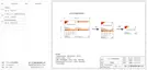
>Select
External ATS
Disable Enable
Mode Select
> < Off
Power Factor
Mode Select
> <
Over-Excited
Power Factor
Mode Select
> <
Under-Excited
Power Factor
Mode Select
> < Curve
Power Factor
Mode Select
> < Q(u)
Power Factor
Mode Select
> < Fixed Q Power
Power Factor
Here you select the baud rate of the external communication protocol, the
default location of 19200 and 485 addresses.
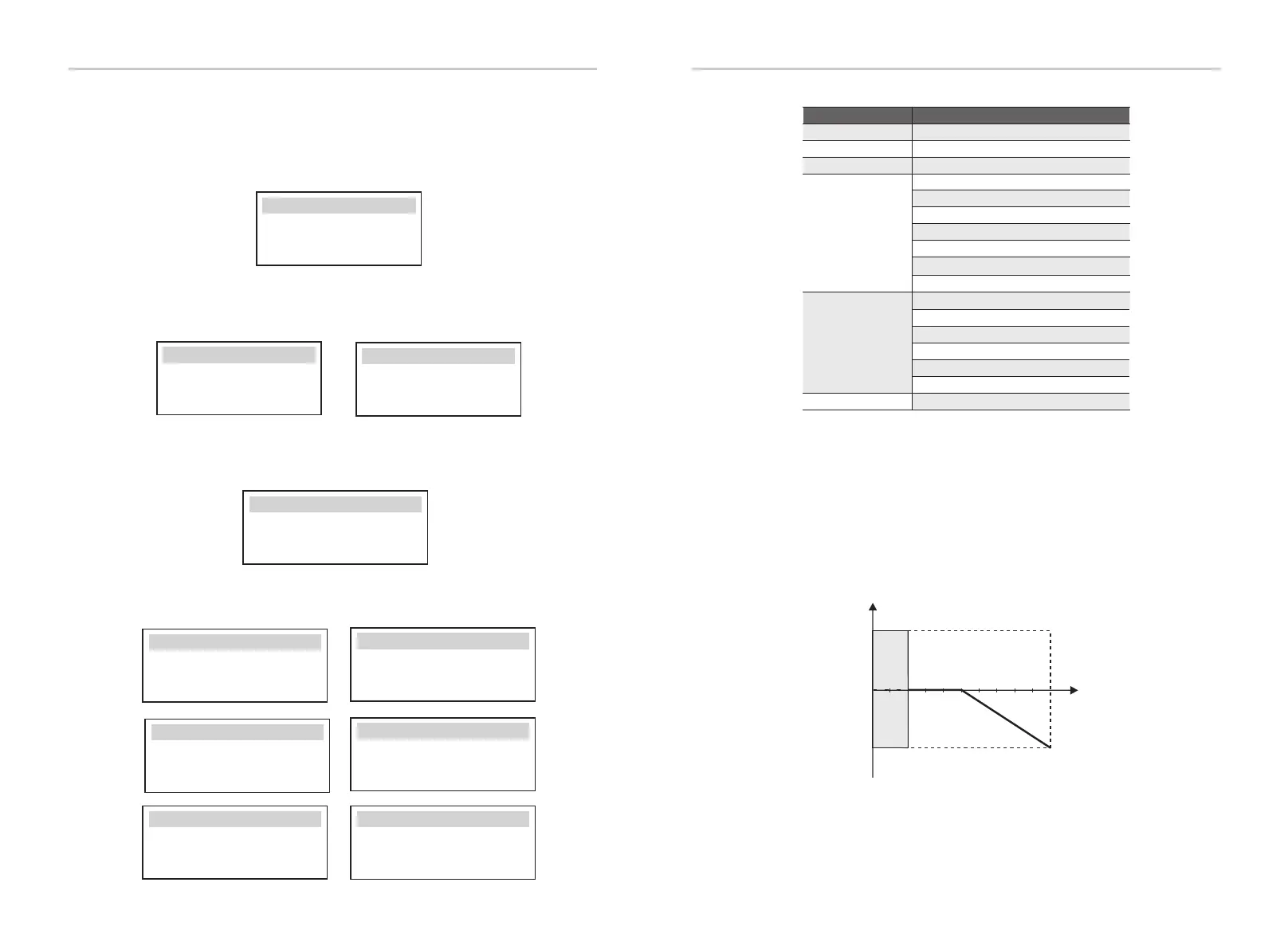
For VDE ARN 4105, the curve cos φ = f(P) should refer to curve A. The set
default value is shown in curve A.
For TOR, the curve cos φ = f(P) should be curve B. The set default value is
shown in curve B.
For CEI 0-21, the default value of PFLockInPoint is 1.05. When Vac> 1.05Vn,
Pac> 0.2 Pn, curve cos φ = f(P) corresponds to curve C.
9) Modbus
Select the functional use of the external communication port. COM for
normal Modbus communication, “EV Charger” for communicating with
the EV Charger, DataHub for communicating with DataHub.
Modbus
COM/EV Charge/Datahub/
>Function Select:
AdaptBoxG2/EVC&AdaptBoxG2
*) If the grid-connected power of the inverter ≦ 4.6kW, the Power Factor
is 0.95 at 1.0 power; if the grid-connected power of the inverter > 4.6kW,
the Power Factor is 0.90 at 1.0 power.
If the Matebox with the inverter has built-in ATS, that is to say the
advanced version, you need to enable this function. In other cases,
disable this function is required.
● Reactive power control, reactive power standard curve cos φ = f(P)
11) Power Factor (applicable to specic countries, please refer to local
grid requirements.)
 Loading...