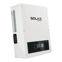
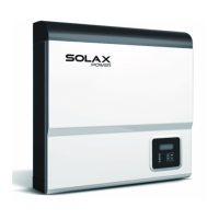
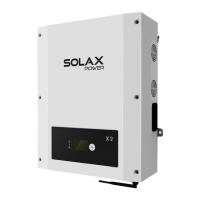
Object
Name
Description
A
B
C
D
E
F
G
H
I
Indicator
LED
Function
button
LCD Screen
Green LED:The inverter is in normal state.
Red LED:The inverter is in fault state.
Yellow LED:The inverter is in communication.
Up button:Move cursor to up side or increase values.
Right button:Move cursor to right side.
Down button:Move cursor to down side or decrease values.
Left botton:Move cursor to left side.
OK:Conrm the selection.
Display the information of the inverter in this LCD screen.
6.2 LCD Function
Menu structure
Menu
New Password
Setting RTC
Comm Address
Connection
Power Factor
Grid Setting
Reset
Safety
AC Measure
DC Measure
Yield
Error Log
Lauguage
Setting
Information
About
Password
6.3 LCD Operation
LCD Graphic Display(Main interface)
●
The main interface is the default interface,the inverter will automatically jump
to this interface when the sustem started up successfully and not operated
for a period of time.
The information of the interface is introduced as below:
The condition or the
value of PV input
Real-time power
The inverter’s output
voltage of each phase
Daily energy
State display
Menu interface
●
The menu interface is a transfer interface for the user to get into the other
interface to nish the settting or get information.
-User can get into this interface by press the “OK” button when the LCD displays
the main interface.
-User can select interface by moving the cursor with the function button,and
press “OK” conrm the selection.
AC Measure
Yield
Language
Information
DC Measure
Error Log
Setting
About
Menu
Main
AC Measure and DC Measure
●
AC measure and DC measure are display interfaces to show the information
of DC input and AC output.
-User can get into the two interfaces by select the “AC Meaure” or “DC
Measure” with cursor on the menu interface and press “OK” to conrm.
-Move the cursor to “Back”and press “OK” to get back to the menu interface.
AC Measure
Back
DC Measure
Back
VacR = 230.0V
VacS = 230.0V
VacT = 230.0V
PacR = 424.3V
PacT = 424.3V
IacR = 1.8A
IacS = 1.8A
IacT = 1.8A
PacS = 424.3V
Fac = 50Hz
Vdc1 = 0.0V
Idc1 = 0.0A
Pdc1 = 0.0W
Vdc2 = 780.3V
Idc2 = 1.8A
Pdc2 = 1273W
33
32
6 Operation Method 6 Operation Method
 Loading...