7
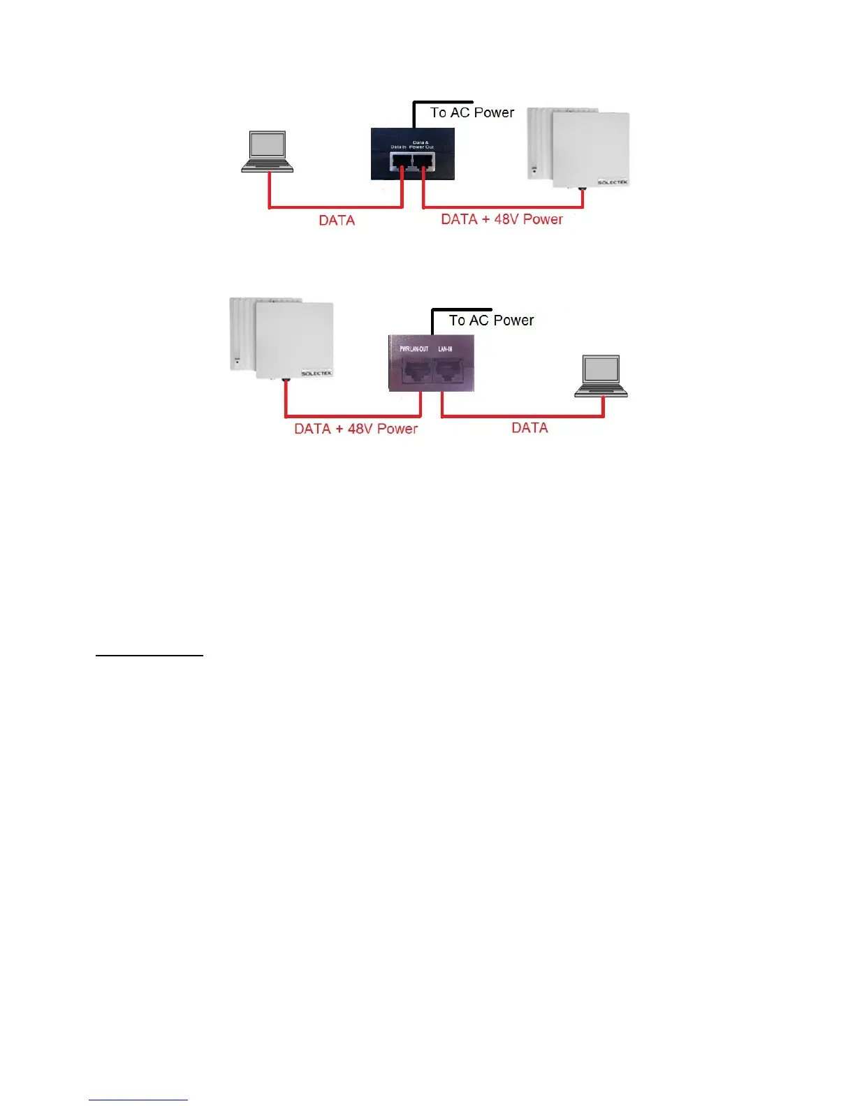
CONNECTION DIAGRAM FOR CLIENT UNITS
CONNECTION DIAGRAM FOR BASE STATION
Please note that the POE/PS units are different for client units and base station and you must
take care to plug in the right CAT5 cables into the POE/PS unit’s RF-45 ports.
• PORT TO THE RADIO UNIT IS INDICATED BY “PWR LAN-OUT” OR “DATA + PWR OUT”
• PORT TO THE PREMISE SWITCH OR COMPUTER IS INDICATED BY “LAN-IN” OR “DATA-IN”
C. INITIAL LOGON
• Open networking properties in your Windows OS. Enter the TCP/IP setup window of your
wired Ethernet adapter properties page. Set the IP addresses to the following values.
Ethernet’s IP Address: 192.168.1.1
Subnet Mask: 255.255.255.0
• Open a Web Browser on the Test PC
• At the URL line, type in the following:
http://192.168.1.100 to access a client unit, or
http://192.168.1.200 to access a base station unit.