6
3. System Connection
A. PORT DESCRIPTIONS (AS5800, AS5810, AND AS5830)
SkyWay Access has the following access ports:
• (1) 10/100/1000 Gigabit Ethernet + Power Connector (AS5800 Base station only)
OR (1) 10/100/ Fast Ethernet + Power Connector (all Client units)
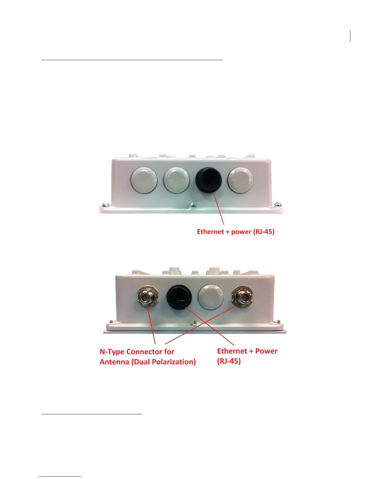
• (2) RF Ports: N type, female (AS5800 Base Station only – Client units come with
integrated antennas)
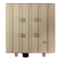
The RJ45 connector is accessed at the bottom of the unit, through a multi-piece waterproofing
feed-through. If included, the RF Ports are accessed on the bottom of the unit, which is shown
below.
Unit Bottom View (Client Unit – AS5810, AS5830)
Unit Bottom View (Base Station – AS5800)
B. CONNECTING THE SKYWAY UNIT
Use the diagram below as a guide to cable your SkyWay test system using a PC or Laptop and a
pair of Cat5 cables. An auto-MDIX feature eliminates the need for cross-over cables.