12
Selecting an Option
For each page of switches, the middle row of meter LEDs indicates, in RED, the currently selected switch such that
Channel 9 LED indicates Switch 1, Channel 10 indicates Switch 2 etc. Pressing the OUTPUT button will cycle through
all switches for that page.
Setting an Option
The current setting of each option in the current page is indicated, in GREEN, by the state of the corresponding LED
in the first row of meter LEDs where the Channel 1 LED indicates the state of Option 1, Channel 2 indicates Option 2
etc. When an option is selected, pressing the INPUT button toggles the state of that option (ON or OFF).
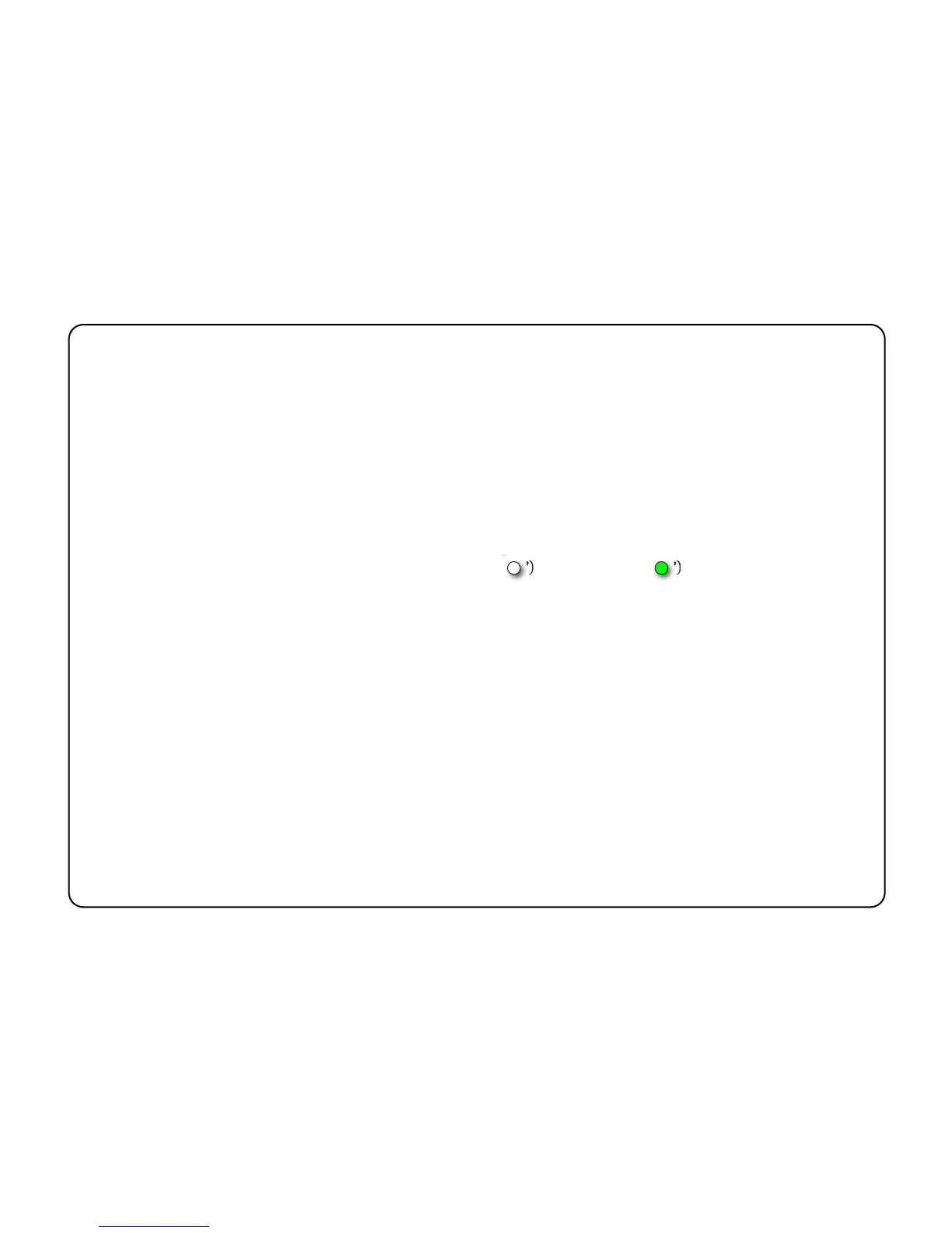
Tables detailing the available options and their default settings will be found on the following pages. In each table
the relevant LED states are indicated as either extinguished (‘ ’) or illuminated (‘ ’).