4. Installation4. Installation
1. The RCD should be in parallel connection between the consumers mains and the solar supply.
2. More than one RCD may be used. Each RCD can protect one or more circuits.
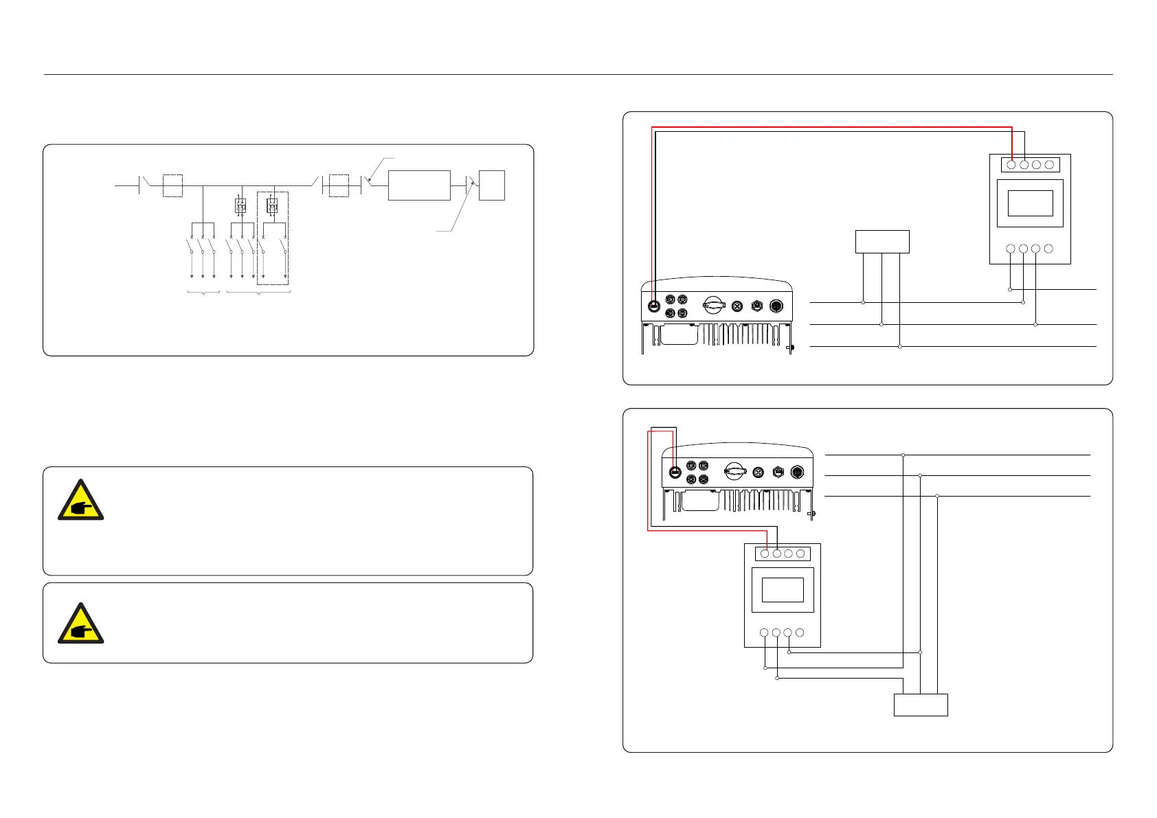
4.3.7 Meter Connection(optional)
The inverter can work with a single phase smart meter to achieve Export Power Management
function and/or 24hour consumption monitoring function.
Below are the connection diagrams of different meters connecting to different locations.
Detailed settings please refer to Section 6.5.12.
Two types of meters are supported:
Direct Insert Type Meter - Max input current 60A (Model:DDSD1352-C)
External CT Type Meter - 120A/40mA CT is supplied (Model: ACR10RD16TE)
Customer can place the order for a suitable meter from Solis Sales Reps.
2-Pin Connector
Pre-made Cable in Meter Package
L N PE
Load
L L' N N'
5 6 7 8
A B
Grid L
Grid N
Grid PE
INV L
INV N
INV PE
Figure 4.22 Direct Insert Type Meter - “Meter in Grid”
INV L
INV N
INV PE
Grid L
Grid N
Grid PE
L N PE
Load
L L' N N'
5
6 7 8
A B
Pre-made Cable
in Meter Package
2-Pin Connector
Figure 4.23 Direct Insert Type Meter - “Meter in Load”
Isolation switch
Solar supply
main switch
Consumers mains
(to grid)
Main
switch
MAIN SWITCHBOARD
Circuits not
protected by
RCDs
Circuits Protected
by RCDs
Isolation device
Inverter with
integral grid
Protection device
Solar
(PV)
array
11
2
Refer to figure 4.21, which is a simple guidance for installing a solar system with PV inverter.
A DC isolator is required to be installed in the system between PV panels with inverter.
Figure 4.21 Guidance for a Simple Installation of an Inverter Solar Energy System
NOTE:
Inverters are classified as "Meter Model" and "CT Model" due to hardware
difference.
Meter Model can only connect a smart meter.
CT Model can only connect a smart sensor.
Please consult Solis Sales Rep before placing the order.
NOTE:
To achieve Export Power Management function, the smart meter can be
installed on either grid side or load side. To achieve 24hour consumption
monitoring function, the smart meter can only be installed on grid side.
.21..20.
4.3.6 Electrical connection diagram
 Loading...