+
-
DC 1
DC 2
DC SWITCH
COM
GRID
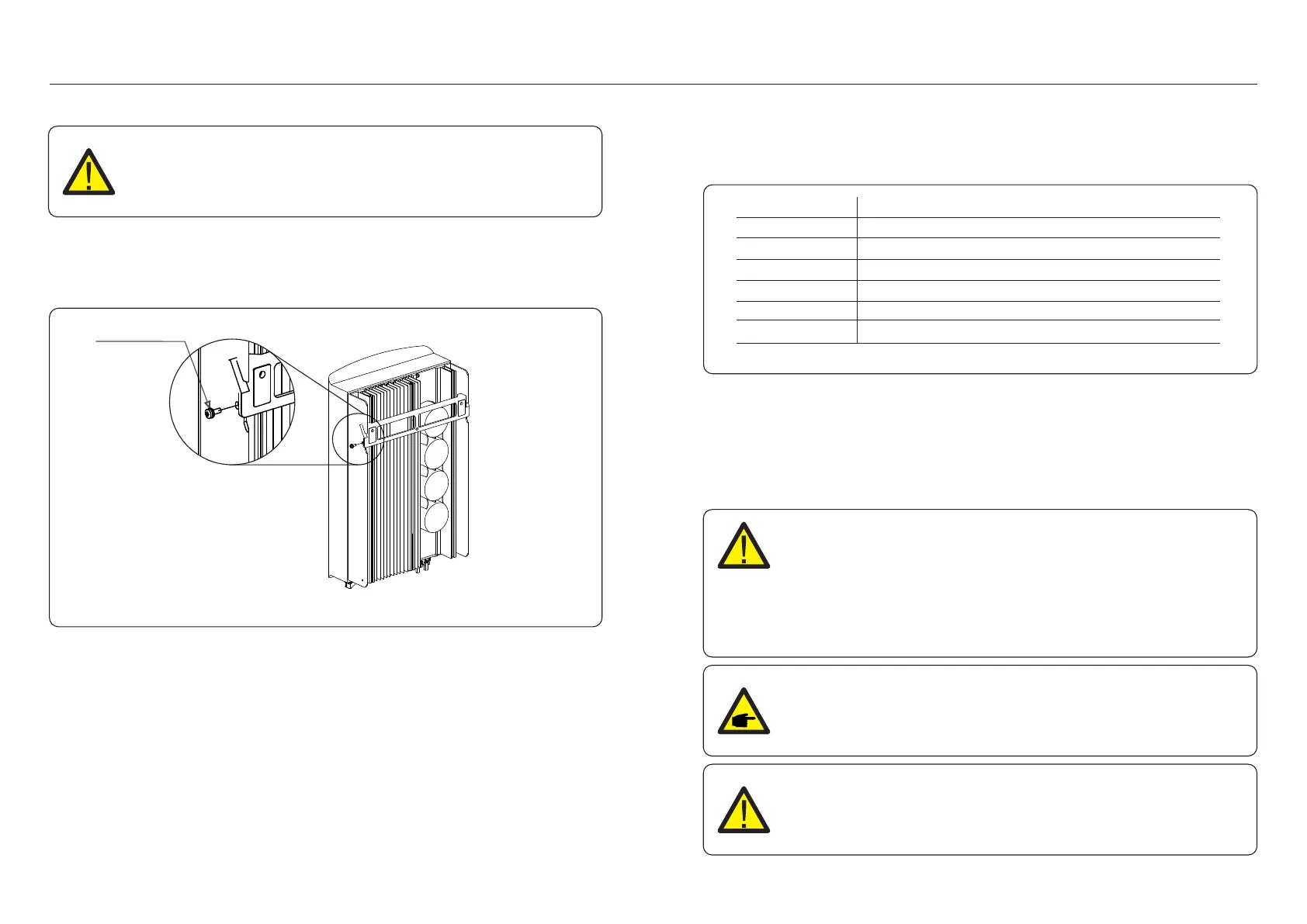
Figure 4.5 Wall Mount Bracket
WARNING:
The inverter must be mounted vertically.
4.3 Electrical Connections
Inverter designs quick-connect terminal, so top cover needn't open during electrical
connection. The sign meaning located the bottom of inverter, as shown below in table 4.1.
All electrical connections are suit for the local or national standard.
Positive DC input terminal
Negative DC input terminal
Connecting terminal of the Grid
Switch of DC input terminals
RJ45 and terminal block for RS485 communication port
DC input terminal
DC input terminal
Table 4.1 Electrical connection symbols
4. Installation4. Installation
The electrical connection of the inverter must follow the steps listed below:
1. Switch the Grid Supply Main Switch (AC) OFF.
2. Switch the DC Isolator OFF.
3. Assemble PV input connector to the Inverter.
4. Lift up the inverter (be careful to avoid body strain), and align the back bracket on the
inverter with the convex section of the mounting bracket. Hang the inverter on the
mounting bracket and make sure the inverter is secure (see Figure 4.5).
5. Use M4*9 screws in accessory to lock the inverter to the mount bracket.
4.3.1 Connect PV side of inverter
Before connecting inverter, please make sure the PV array open circuit
voltage is within the limit of the inverter.
NOTE:
Before connection, please make sure the polarity of the output voltage of
PV array matches the“DC+”and“DC-”symbols.
WARNING:
Please don’t connect PV array positive or negative pole to the ground,
it could cause serious damages to the inverter.
.12. .13.
Locking screws
Maximum 550Vdc for
S6-GR1P2.5K
Maximum 600Vdc for
S6-GR1P3K, S6-GR1P3.6K, S6-GR1P4K,
S6-GR1P4.6K, S6-GR1P5K, S6-GR1P6K

 Loading...