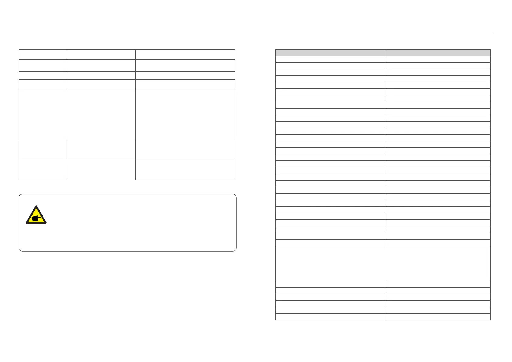
9. Specifications8. Troubleshooting
Screen OFF
with DC applied
Inverter internally damaged
1.Do not turn off the DC switches as it will
damage the inverter.
2.Please wait for the solar irradiance reduces
and confirm the string current is less than
0.5A with a clip-on ammeter and then turn
off the DC switches.
3.Please note that any damages due to wrong
operations are not covered in the device
warranty.
DCinj-FAULT
High DC injection current
1.Check AC and DC connection
2.Check inverter inside cable connection.
1.Restart inverter or contact installer.
1.Restart inverter or contact installer.
Alarm Message
Failure description
Solution
ILeak-PRO
01/02/03/04
Leakage current protection
RelayChk-FAIL
Relay check fail
Table 8.1 Fault message and description
NOTE:
If the inverter displays any alarm message as listed in Table 8.1; please
turn off the inverter (refer to Section 5.2 to stop your inverter) and wait
for 5 minutes before restarting it (refer to Section 5.1 to start your inverter).
If the failure persists, please contact your local distributor or the service
center.
Please keep ready with you the following information before contacting us.
1. Serial number of Solis Single Phase Inverter;
2. The distributor/dealer of Solis Single Phase Inverter (if available);
3. Installation date.
4. The description of problem (i.e. the alarm message displayed on the LCD and the status
of the LED status indicator lights. Other readings obtained from the Information submenu
(refer to Section 6.2) will also be helpful.);
5. The PV array configuration (e.g. number of panels, capacity of panels, number of strings
, etc.);
6. Your contact details.
AFCI self-detection
(model with AFCI
module)
AFCI module self-detect fault
1.Restart inverter or connect technician.
Arcing protection
(model with AFCI
module)
Detect arc in DC circuit
1. Check inverter connection whether arc
exists and restart inverter.
.47..46.
45...55 or 55...65
Max. DC input voltage (Volts)
MPPT voltage range (Volts)
Max. input current (Amps)
MPPT number/Max input strings number
Rated grid voltage (Volts)
Rated output current (Amps)
Max. output current (Amps)
Power Factor (at rated output power)
Operating frequency range (Hertz)
Max.efficiency
EU efficiency
Model
Dimensions
Weight
Topology
Operating ambient temperature range
310W*543H*160D (mm)
550
50/60
Transformerless
Rated output power (Watts)
Max. output power (Watts)
Max. apparent output power (VA)
THDi (at rated output power)
<3%
50...450
Startup voltage (Volts)
60
Max short circuit input current (Amps)
Rated DC voltage (Volts)
Rated grid frequency (Hertz)
14+14
22+22
2/2
97.3%
96.5%
250
2500
2800
2800
11.4/10.9
13.3
S6-GR1P2.5K
11kg
1/N/PE, 220/230
>0.99 (0.8 leading - 0.8 lagging)
-25℃.. .+60℃
Grid connection standard
VDE-AR-N 4105 / VDE V 0124, EN 50549-1,
VDE 0126 / UTE C 15 / VFR:2019, G98 or G99,
RD 1699 / RD 244 / UNE 206006 / UNE 206007-1,
CEI 0-21, C10/11, NRS 097-2-1, TOR,
EIFS 2018.2, IEC 62116, IEC 61727, IEC 60068,
IEC 61683, EN 50530, MEA, PEA
Ingress protection
Noise emission (typical)
Cooling concept
Max.operation altitude
IP66
<20 dBA
Natural convection
Relative humidity
0~100%
Display
Communication connections
Warranty Terms
LCD, 2×20 Z.
5 Years (Extend to 20 Years)
Safety/EMC standard
IEC/EN 62109-1/-2, IEC/EN 61000-6-2/-3
DC connection
AC connection
MC4 connector
Quick connection plug
Self consumption (night) <1 W
4000m
RS485, Optional: Wi-Fi, GPRS, USB*
Optional USB* :only for the brazilian market

 Loading...