Introduction
SP25-55_User Manual_B8_EN_2012-11-06 10/32
3 Introduction
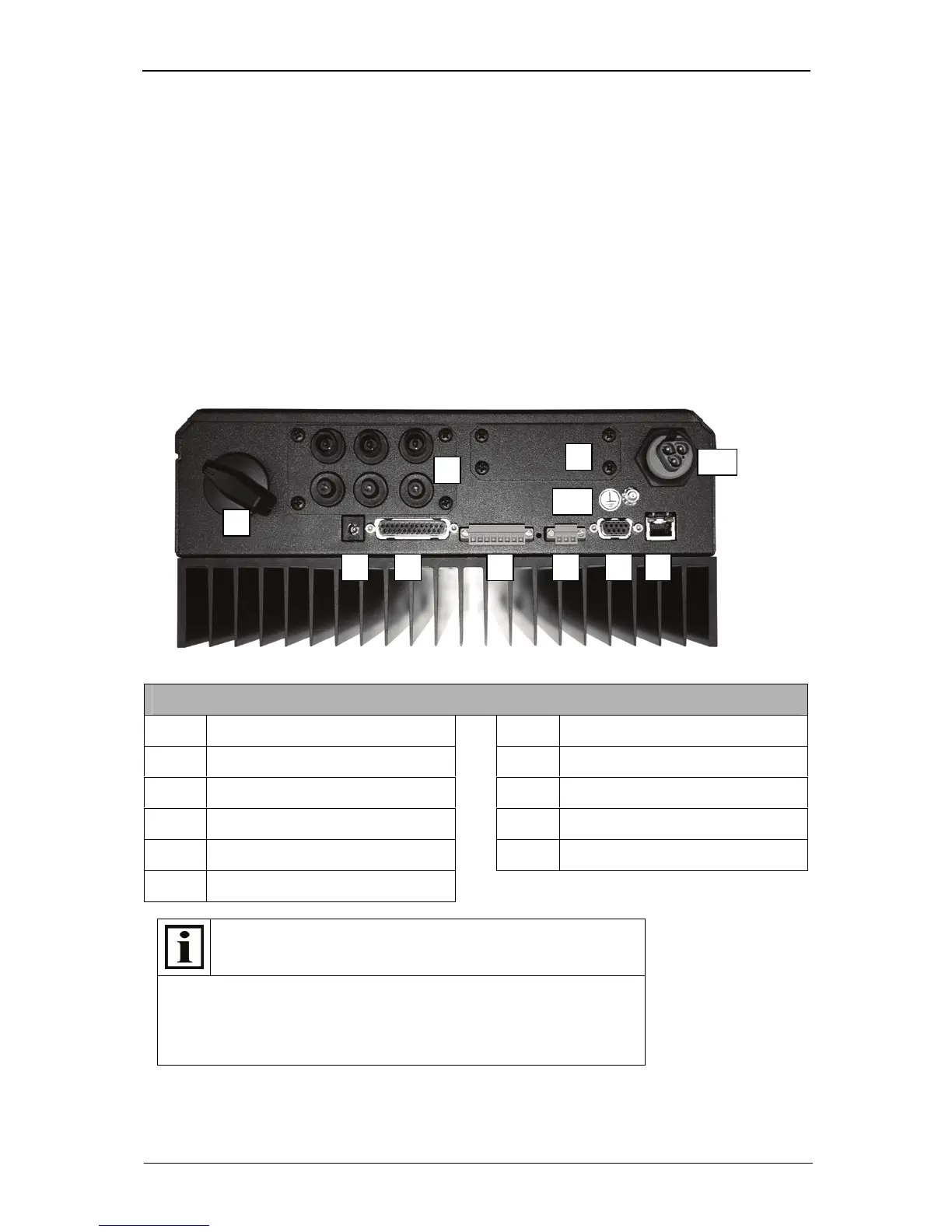
Each SOLPLUS inverter features a number of interfaces and communication ports via which the data
of the inverter can be read out. A total of approximately 300 inverter parameters can be read out.
The data provided by the inverter are divided into the following categories:
1 Yield and display values: These values represent the instantaneous values of the inverter.
They are actual values and display values that cannot be altered.
2 Setting values: These are values that can be set and altered individually. Depending on the
importance and meaning of the parameters, these values can be set by the final customer, the
fitter or the utility company. For security purposes, different password levels are incorporated.
4 General communication features
Note
An external plug-in AC adapter can be used to provide an auxiliary
power supply.
12 V DC
300 mA, with built-in modem 1 A
Connector, 5.5 x 2.1 pin + (positive), sheath – (negative)
SOLPLUS 25 - 55
1 RS232 X1 7
Ethernet X7