Operating states
SP25-55_User Manual_B8_EN_2012-11-06 13/32
5 Operating states
The operating states of the SOLPLUS 25 - 55 inverters are indicated by means of a light-emitting
diode (LED) and on the display.
The LED has two colours and indicates the instantaneous operating state of the inverter. The actual
operating state is indicated on the display.
For the operating state to be identified, the DC side of the inverter must be connected to the PV
modules and a minimum voltage of approx. 280 V must be input into the inverter.
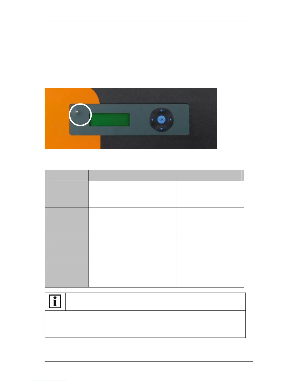
Example SOLPLUS 25 – 55 display
Meaning the operating states
What to do in the case of a fault
If the LED on the inverter lights up red or red/green, read up the fault description in the
Installation Instructions manual or note down the warning/alarm/fault message indicated on the
display and contact your fitter.
It is best if you read out all the data supplied by the SOLPLUS inverter: the last fault displayed,
fault memory, data logger and list of all parameters.
LED Explanation Display content
Constantly lit
green
Grid-feed mode SOLPLUS 50
PAC=2510 W
Grid-feed mode
Menu ►
Flashing green Initialisation or standby, e.g. because the
voltage of the solar generator is too low
SOLPLUS 50
PAC=0W
Initialisation
Menu ►
Flashing red/green