Integrated Installation Monitoring
SP25-55_User Manual_B8_EN_2012-11-06 21/32
15 Integrated Installation Monitoring
Each inverter is equipped with an integrated installation monitoring function. This means it regularly
performs a number of checks and warns the installation's owner in the event of a critical condition
arising or variations in yield occurring.
If the inverter detects a critical condition or yield variation, it continues to function – insofar as this is
possible – but outputs an alarm both visually and acoustically. An alarm is given by the following
means:
• Acoustic alarm: the alarm horn integrated in the inverter emits an intermittent alarm tone. It
sounds for half a second every second. The alarm horn can be switched off by pressing any
button.
• The LCD display switches on. The word "Alarm" and the cause of the alarm are displayed
alternately in the third line of the basic (start) screen.
• The LED on the cover of the inverter flashes red and green alternately.
• The number of the alarm is also displayed in parameter 155 (in the Installation Monitoring
menu).
If the inverter is being operated via a communication port, a file that is continuously written to and has
the name "File 14 Alarms" can be read out. This file is empty in the morning and, insofar as (several)
alarms occur during the course of the day, has the various alarm texts, additional explanations and the
times at which the alarms occurred written to it.
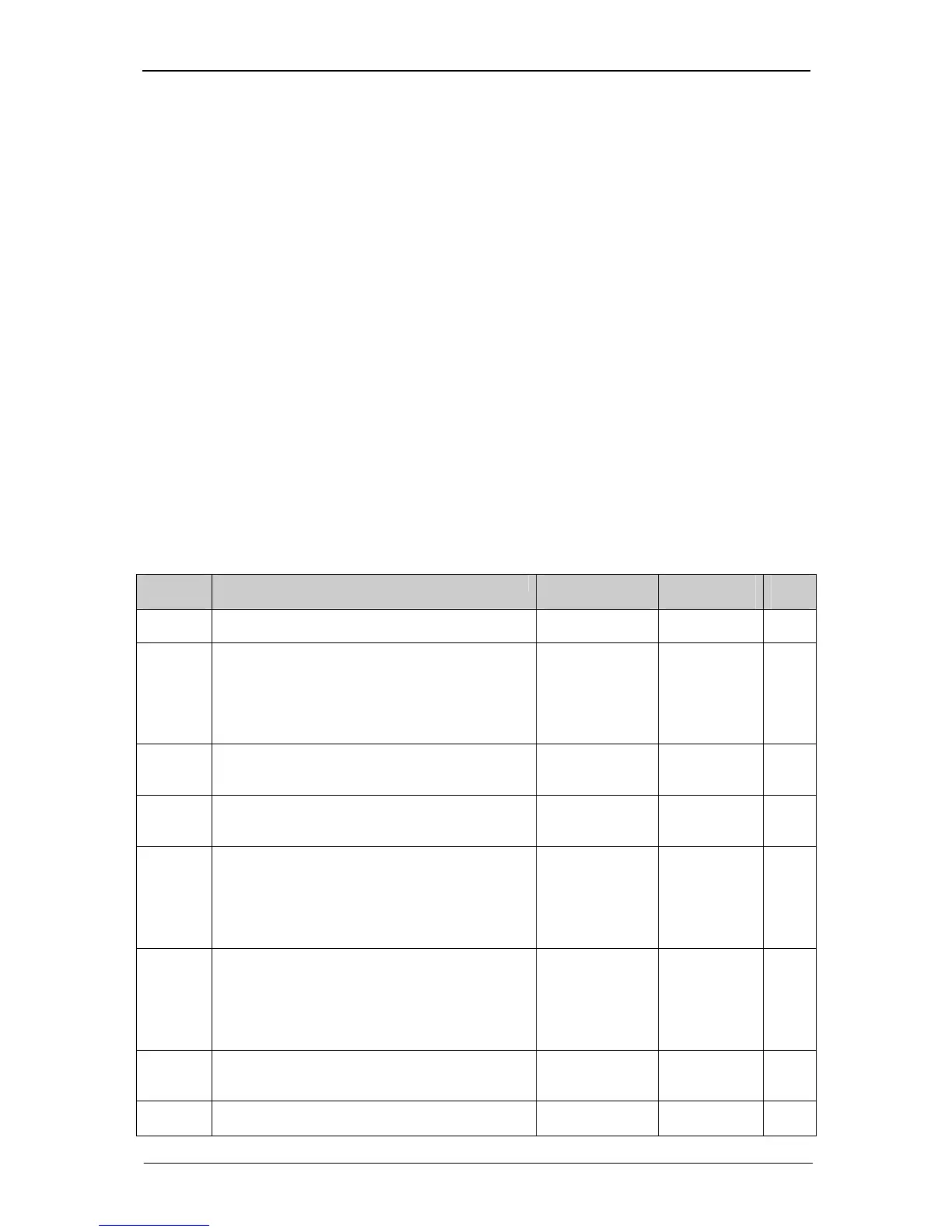
15.1 Possible causes of an alarm
The following causes of an alarm are possible:
Alarm
number
Description Dependent
upon
Attribute
represents:
Bit of
P279
0 No alarm - -
1 UAC not okay. This text is displayed if the
mains voltage is lower than the minimum alarm
threshold or higher than the maximum alarm
threshold for the mains voltage for longer than
2 minutes.
P50: Max.
mains voltage
alarm threshold;
P52: Min. mains
voltage alarm
threshold
Value of the
mains
voltage
0
2 UDC too high. This text is displayed if the DC
voltage is higher than the maximum DC voltage
alarm threshold for longer than 1 minute.
P58: Max. DC
voltage alarm
threshold
Value of the
DC voltage
1
3 Inverter too hot. This text is displayed if the
inverter temperature is higher than 65°C for
longer than 2 minutes.
Value of the
inverter
temperature
2
4 Yield sensor. This text is displayed if the yield
monitoring function (see section on yield
monitoring) has detected during the last 5 days
a variation between the yield of the inverter and
the "theoretical yield" of the sensor that
exceeds the value of P280.
P280: Yield
variation
- 3
5 Yield slaves. This text is displayed if the yield
monitoring function (see section on yield
monitoring) has detected during the last 5 days
a variation between the yield of the inverter and
the yield of the slave that exceeds the value of
P280.
P280: Yield
variation
Number of
the slave
4
6 Communication. This text is displayed if data
communication between the master and the
slaves is disrupted.
Number of
the slave
5
7 Mains frequency. This text is displayed if the
variation from the rated mains frequency of
P76: Max.
alarm threshold
Value of the
mains
6