22
INSTALLING THE CONNECTIVITY MODULE
FIRST
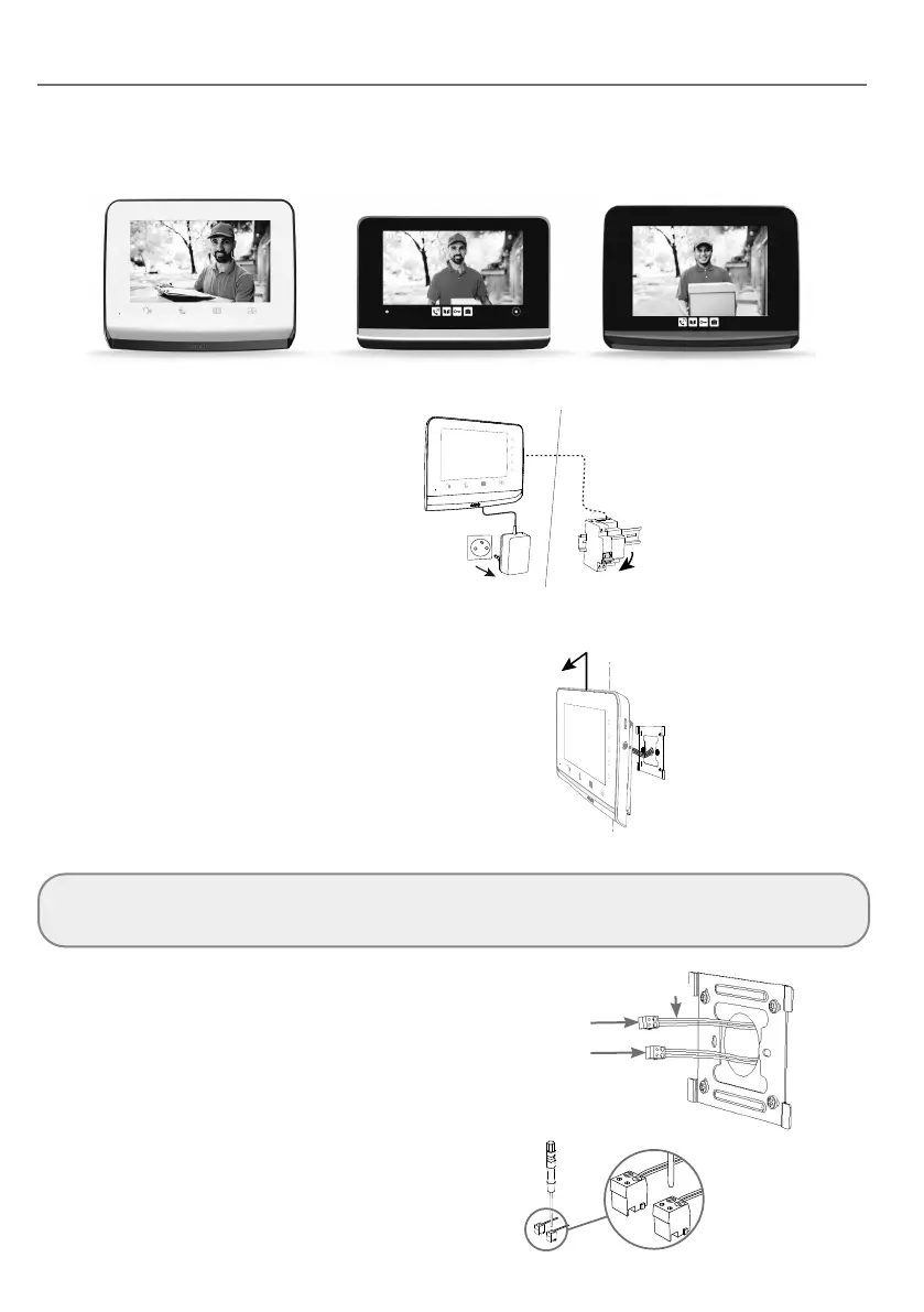
• Identify your installed indoor monitor:
• Power o your video door phone.
DIN rail power supply
ref. 9026469
UNINSTALLING THE INDOOR MONITOR
• Unhook the indoor monitor from its mounting
bracket by sliding it upwards.
• Leave the mounting bracket in place.
• Memorise or take a photo of the connection
on the back of the monitor, in order to identify
the power supply cables (24V DC) and the call
station (CS).
• Without undoing the blue connectors on the cables, disconnect all the connectors to release the monitor.
Important: if you have a second monitor, this is incompatible with the connectivity module.
You will no longer be able to deal with visitors calling at the call station. Conversely, you can continue to use it to control
Somfy RTS/io equipment, or to run scenarios (V®500 PRO io monitor only).
• Using the photo taken:
- Identify the 2 power supply wires (24V DC
terminal block) via the polarity (+ and -).
- Identify the 2 call station wires (CS terminal
block). The polarity is irrelevant.
Call station (CS)
Power supply (24V DC)
+/-
• Using the screwdriver supplied, unscrew the
blue connectors from the identified cables.
These are no longer reusable.
V®350 V®500 V®500 PRO io