3
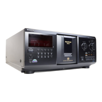
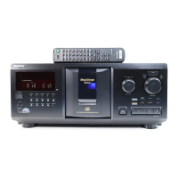
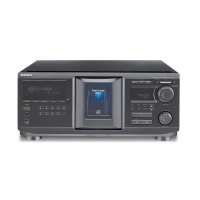
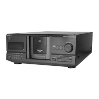
CDP-CX355
TABLE OF CONTENTS
SECTION 1
SERVICING NOTE
NOTES ON HANDLING THE OPTICAL PICK-UP BLOCK
OR BASE UNIT
The laser diode in the optical pick-up block may suffer electrostatic
break-down because of the potential difference generated by the
charged electrostatic load, etc. on clothing and the human body.
During repair, pay attention to electrostatic break-down and also
use the procedure in the printed matter which is included in the
repain parts.
The flexible board is easily damaged and should be handled with
care.
NOTES ON LASER DIODE EMISSION CHECK
The laser beam on this model is concentrated so as to be focused on
the disc reflective surface by the objective lens in the optical pick-
up block. Therefore, when checking the laser diode emission,
observe from more than 30 cm away from the objective lens.
The emission check enables continuous checking of the S curve.
LASER DIODE AND FOCUS SEARCH OPERATION
CHECK
Carry out the “S curve check” in “CD section adjustment” and check
that the S curve waveform is output three times.
1. SERVICING NOTE·····················································3
2. GENERAL ···································································6
3. DISASSEMBLY ··························································7
3-1. Case··············································································· 8
3-2. Bracket (F. W. ) ····························································· 8
3-3. Front Panel Assy ··························································· 9
3-4. DISP Board, JOG Board, KEYBOARD Board ············ 9
3-5. LED Board, Guide (Door. T) ······································ 10
3-6. Table (300) Assy, Cover (P.T.) ···································· 10
3-7. D. MOTOR Board, Door Motor Assy (M83) ············· 11
3-8. D. SW Board······························································· 12
3-9. Base (Door, Gear) Assy ·············································· 13
3-10. Pop-up Assy ································································ 13
3-11. D. SENS (OUT) Board ·············································· 14
3-12. T. SENS Board···························································· 14
3-13. D. SENS (IN) Board ·················································· 15
3-14. Back Panel Section ····················································· 15
3-15. MAIN Board, JACK Board ········································ 16
3-16. POWER Board···························································· 16
3-17. Bracket (Top) , BU Assy ············································· 17
3-18. BU Holder Assy ·························································· 17
3-19. BD Board, Optical Device (KSM-213 BFN)·············· 18
3-20. L. SW (A) Board, L. SW (B) Board ························· 19
3-21. CDM Assy ·································································· 20
3-22. Motor Assy (Loading) (M82) ,
Motor Assy (Table) (M81) , L. T. MOTOR Board ····· 20
4. SERVICE MODE ···························································· 21
5. TEST MODE ···································································· 25
5-1. ADJ Mode··································································· 25
5-2. Key and Display Check Mode ···································· 25
6. ADJUSTMENTS ···························································· 26
6-1. Mechanical Adjustments············································· 26
6-2. Electrical Adjustment·················································· 28
7. DIAGRAMS ······································································ 31
7-1. Block Diagrams – BD Section –································· 32
– MAIN Section –······················································· 33
7-2. Printed Wiring Board – BD Section – ························ 34
7-3. Schematic Diagram – BD Section – ··························· 35
7-4. Printed Wiring Board – MAIN Section – ··················· 36
7-5. Schematic Diagram – MAIN Section (1/2) – ············· 37
7-6. Schematic Diagram – MAIN Section (2/2) – ············· 38
7-7. Printed Wiring Board – T.SENS Section – ················· 39
7-8. Printed Wiring Board – D.SENS (IN) Section – ········ 39
7-9. Printed Wiring Board – D.SENS (OUT) Section – ···· 39
7-10. Schematic Diagram – SENSOR Section – ················· 39
7-11. Printed Wiring Board – DISPLAY Section – ············· 40
7-12. Schematic Diagram – DISPLAY Section – ················ 41
7-13. Printed Wiring Board – JOG Section –······················· 42
7-14. Schematic Diagram – JOG Section – ························· 43
7-15. Printed Wiring Board – POWER Section – ················ 44
7-16. Schematic Diagram – POWER Section – ··················· 44
7-17. Printed Wiring Board – JACK Section – ···················· 45
7-18. Schematic Diagram – JACK Section ·························· 45
7-19. Printed Wiring Board – SWITCH/MOTOR Section – ··· 46
7-20. Schematic Diagram – SWITCH/MOTOR Section – ····· 46
7-21. IC Pin Functions ························································· 50
8. EXPLODED VIEWS ······················································ 54
8-1. Case Section································································ 54
8-2. Chassis Section 1 ························································ 55
8-3. Chassis Section 2 ························································ 56
8-4. Back Panel Section ····················································· 57
8-5. Front Panel Section ····················································· 58
8-6. Mechanism Section 1 (CDM54-K1BD45)
(Pop-up Assy, Base (Door. Gear) Assy)······················ 59
8-7. Mechanism Section 2 (CDM54-K1BD45) ················· 60
8-8. Mechanism Section 3 (CDM54-K1BD45) ················· 61
8-9. Mechanism Section 4 (CDM54-K1BD45) ················· 62
8-10. Optical Pick-up Section (BU-K1BD45) ····················· 63
9. ELECTRICAL PARTS LIST ······································· 64