EasyManua.ls Logo

Sony CDX-51 - Page 63

Sony CDX-51
68 pages
Print Icon
To Next Page IconTo Next Page
To Previous Page IconTo Previous Page
Loading...
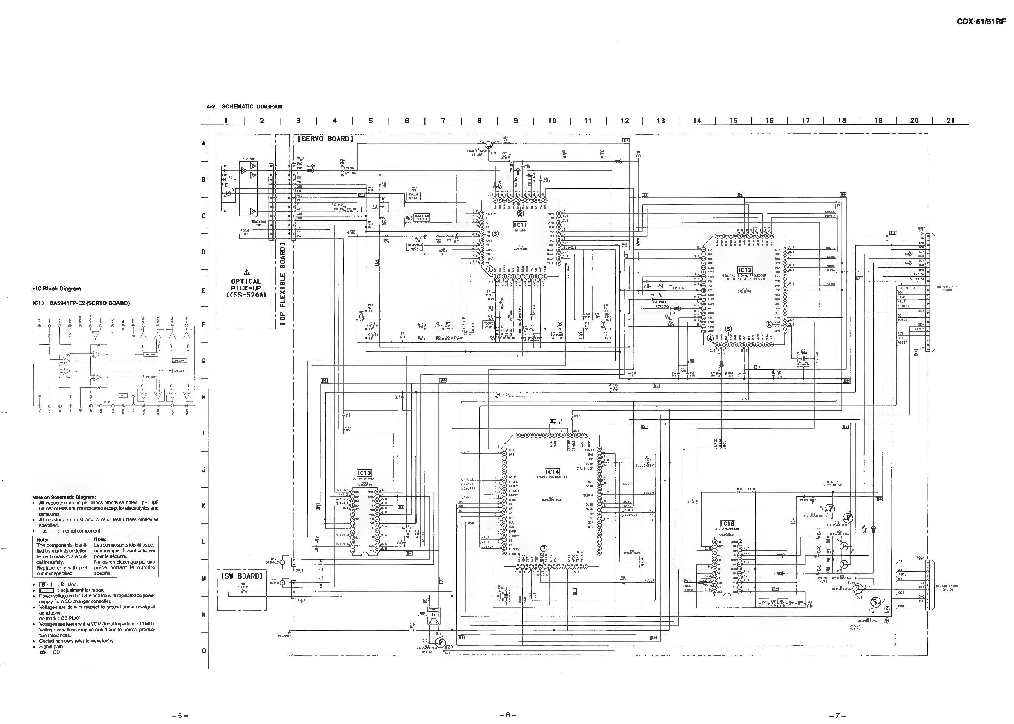
CDX-51/51RF
4-2.
SCHEMATIC
DIAGRAM
1
2 3
4
5
a
6
7
8
| |
9
|
10
11
12 13 14
15
16
17
18
|
19
|
20
|
21
1
ere
a
e
-
3
2
es
aes
A
uw
|
[SERVO
BOARD]
;
Ps
2
=
-
=
—
z
-
=
he
at
SS
ened,
5.8
a
ee
16
'
tate
1
|
ous
sary
a)
rm
®
ss
7
a
EB
:
*
=
>
Ba
Pot
=
CTE
=
:
=
>
E
2
105
Po
B
i)
vA
=
ul
so
=
wf"
ue
'
a
vee
Ye
*
Ce
orrser
w
F
Ria
100,
-
fe
=
G4
I
KC
ab
380
Ra
th
|
cx
c
one
Facer
if
i
TRACKING
=
oreset
=
cack
io
cant
Focus
ale
F-
Pit
|
=.
a
a
——t
|
cue
-
ms
i
a
|
“wv
D
Q!t
Pa
al
|%
arf
(|e,
PA
:
oa
H
=<
at
oar
19
|
2.
TCH
r]
SENS
a
=e!
CSTE
4
|
Pa
|
|
ce
rc12
zal
|
2s
1
:
SVB
nal
*
IC
Block
Diagram
1
Pp
cts
=
mo
tetas
So
eeeeesaae
ee
i
Ea
E
ICK-UP
|i
=
"
sn
aS
(KSS-520A)
|
|
2
FR
;
scon
[C13
BAS941FP-E2
(SERVO
BOARD)
alt
ie
ae
t
*
Gone
4
(jay
gt
at
som
'
1a
yt
of
(a
sy
‘1
:
Ss
{se
5
us
qeAPMA
Wt
a:
Lose
renee
re
1
robitsy
mug
oe
B&)
|S
E
Focus]
a
r
th
+
a
Lf
7s,
aL
ey
caon]?|
aI
|
Cae
3
wy
ie
r
Bee
4s
‘ee
tr
amt
ie
es
Pst
I?
|
al
car
1
RESET
G
2
a
ees
Rat
|
gt
10%
=
rs
a
4
1
t
Ee
fy
4
aba
ey
pe
|
ia
L
y
3
H
etl
lt
Soh
oat
o
S—@
o—O
é
&
t
°
|
z
ie
oe
a
ee
ee
Ge
sg
se
as
tak
os
BY
CEE
ercecues
Sahel
t
'
et
I
'
"8
i
|
f
i
ors
Wi
era]
2.
u.chEck
sehvo
BRIvER
cocux
SYSTEM
CONTROLLER
i
nel
wollen
cox
a
S008
H
Note
on
Schematic
Diagram:
rac
ae
ad
wre
ohive
*
All
capacitors
are
in
iF
unless
otherwise
noted.
pF:
ppF
SENS
as
7
as
ciara
(
50
WV
or
less
are
not
indicated
except
for
electrolytics
and
K
8
air
ag
u
supa
oa
t
tantalums.
'
L.
51
eock
Bat
Pues
Oa
©
All
resistors
are
in
Q
and
‘/,
W
or
less
unless
otherwise
ne
a
(ee
re
he
<
ot
i
specified.
peed
2528
‘1
i
Pees
eicain
POP
R
to
a
a7
a
—
erentianss
Note:
Note:
1
‘i
8/4
CONVERTER
Gy
rane
eal
g
g
The
components
identi-
|
Les
composants
identifiés
par
L
iy
|
realbthee,
1B
acsiff-ries
'
fied
by
mark
A\
or
dotted
|_une
marque
A\
sont
critiques
i
|
HT
fine
with
mark
Aare
criti-
|
pour
la
sécurité.
:
:
cal
for
safety.
Ne
les
remplacer
que
par
une
a
ont?
=
©
e000
Sey
roads
|
Bm
2
Replace
only
with
part
|
piéce
portant
le
numéro
“oD
tet
Ed
aR
EEE
[¥]
|
He
f
o
number
specified.
spécifié.
[sw
B
=.
ogy
at
a
—#
J
a
mm
ie
BOARD]
‘mn
+
[BE]
:B+Line.
M
2
Gy
.
{
As)
i
+
[1
:adjustment
for
repair.
Ein
ars
RESEY
oxTA
a19,
20.
arcsaile-nies
_
«Power
voltage
is
de
14.4
V
and
fed
with
regulated
dc
power
!
t
a
wit
B
=
supply
from
CD
changer
controller.
a
i
4
ara
r146
err
soi
moana
*
Voltages
are
dc
with
respect
to
ground
under
no-signal
ba
oe
Fa
conditions.
———
.
P
”
oe
5
no
mark
:
CD
PLAY
N
aT
oe
=
ge
Bly
mel
bee
Voltages
are
taken
with
a
VOM
(Input
impedance
10
MQ).
'
5
;
Voltage
variations
may
be
noted
due
to
normal
produc-
qe
am
Bs
tion
tolerances.
=
—i
t
orn
2riee
ABR
©
Gircled
numbers
refer
to
waveforms.
Buse
=
—
i
swiren
«
Signal
path.
0.2,
1
>
:cD
0
anna
|
05
>
=
=
3
sar
St