3
CDX-MP30
TABLE OF CONTENTS
1. GENERAL
Location of controls (US model)............................................ 4
Location of controls (AEP and E model) ............................... 4
Connections (US and E model) .............................................. 5
Connections (AEP model)...................................................... 6
2. DISASSEMBLY
2-1. Cover ............................................................................ 7
2-2. Panel (1) Assy, Sub ...................................................... 8
2-3. CD Mechanism Block (MG-393M-121)...................... 8
2-4. MAIN Board ................................................................ 9
2-5. Heat Sink ...................................................................... 9
2-6. Chassis (T) Sub Assy ................................................. 10
2-7. Lever Section.............................................................. 10
2-8. SERVO Board ............................................................ 11
2-9. Shaft Roller Assy ....................................................... 11
2-10. Floating Block Assy ................................................... 12
2-11. Sled Motor Assy (M901),
Optical Pick-up (KSS-720A) ..................................... 12
MAIN BOARD (CNP701)
SERVO BOARD (CN1)
3. DIAGRAMS
3-1. Block Diagram –CD Section–.................................... 13
3-2. Block Diagram –MAIN Section– .............................. 14
3-3. Block Diagram –DISPLAY Section–......................... 15
3-4. Printed Wiring Boards –CD Section– ........................ 16
3-5. Schematic Diagram –CD Section (1/2)–.................... 18
3-6. Schematic Diagram –CD Section (2/2)–.................... 19
3-7. Printed Wiring Board –MAIN Section–..................... 20
3-8. Schematic Diagram –MAIN Section (1/2)–............... 21
3-9. Schematic Diagram –MAIIN Section (2/2)– ............. 22
3-10. Printed Wiring Board –DISPLAY Section– ............... 23
3-11. Schematic Diagram –DISPLAY Section–.................. 24
3-12. IC Pin Descriptions .................................................... 29
4. EXPLODED VIEWS
4-1. Chassis Section .......................................................... 34
4-2. Front Panel Section .................................................... 35
4-3. CD Mechanism Section (1) (MG-393M-121) ............. 36
4-4. CD Mechanism Section (2) (MG-393M-121) ............. 37
4-5. CD Mechanism Section (3) (MG-393M-121) ............. 38
5. ELECTRICAL PARTS LIST········································· 39
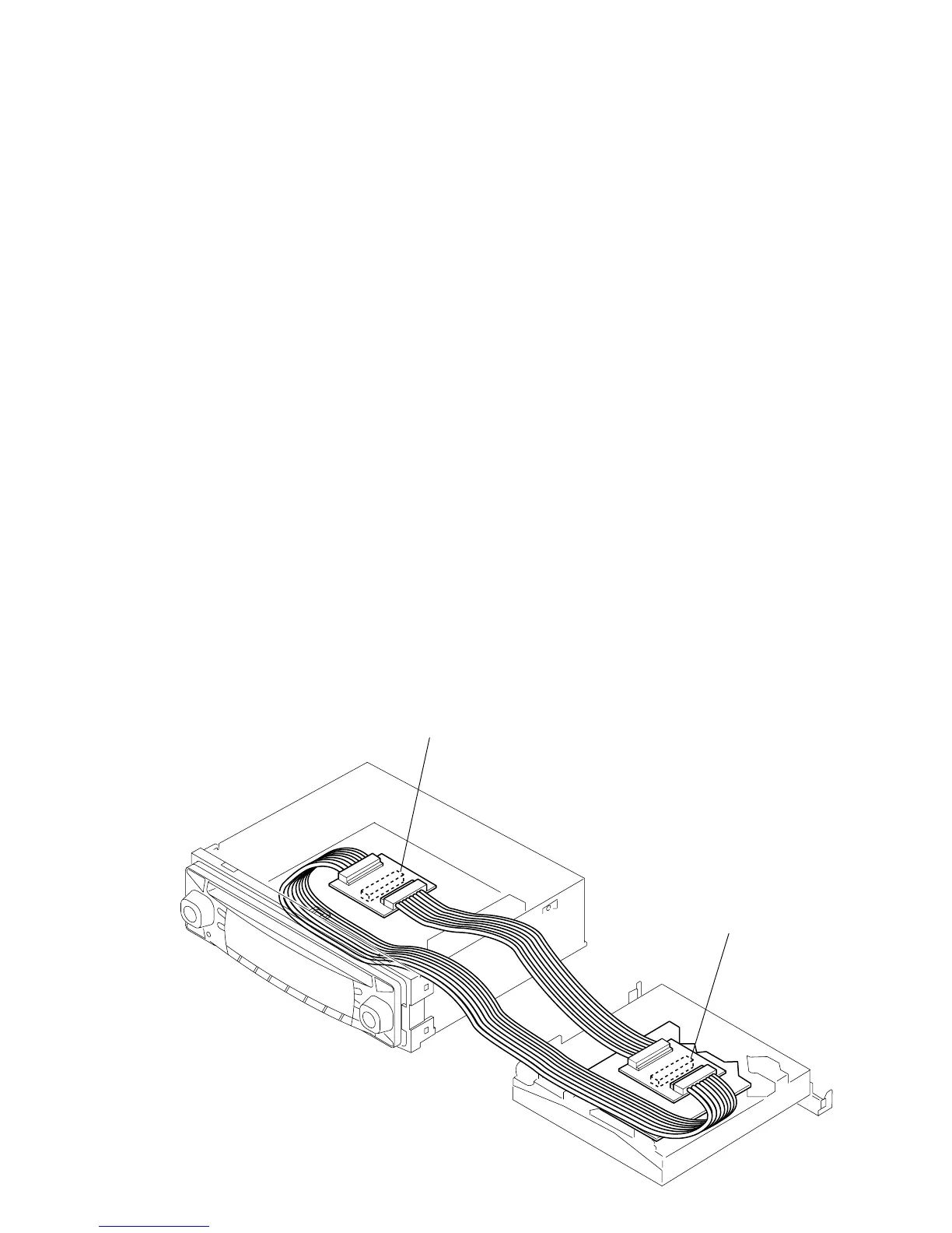
EXTENSION CABLE AND SERVICE POSITION
When repairing or servicing this set, connect the jig (extension cable)
as shown below.
• Connect the MAIN board (CNP701) and the SERVO board (CN1)
with the extension cable (Part No. J-2502-062-1).
 Loading...