40
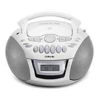
CFD-E75L
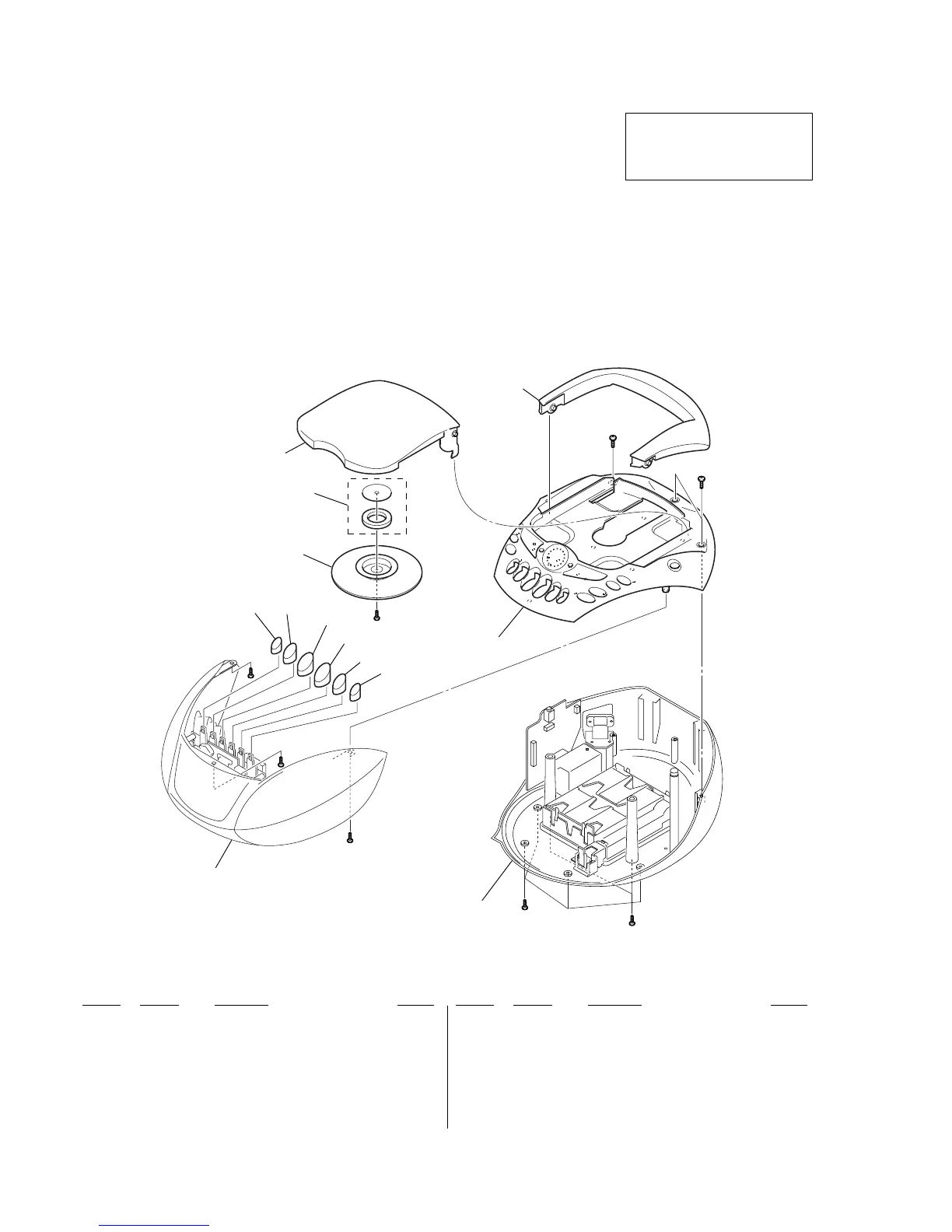
7-1. CABINET SECTION
SECTION 7
EXPLODED VIEWS
• Items marked “*” are not stocked since they
are seldom required for routine service. Some
delay should be anticipated when ordering
these items.
• The mechanical parts with no reference num-
ber in the exploded views are not supplied.
• Hardware (# mark) list and accessories and
packing materials are given in the last of the
electrical parts list.
NOTE:
• -XX and -X mean standardized parts, so they
may have some difference from the original
one.
• Color Indication of Appearance Parts
Example:
KNOB, BALANCE (WHITE) . . . (RED)
↑↑
Parts Color Cabinet's Color
Ref. No. Part No. Description Remark
Ref. No. Part No. Description Remark
1 3-229-988-01 KNOB (REC)
2 3-229-987-01 KNOB (PLAY)
3 3-229-985-01 KNOB (REW)
4 3-229-986-01 KNOB (FF)
5 3-229-984-01 KNOB (STOP/EJECT)
6 3-230-316-01 KNOB (PAUSE)
7 3-019-395-01 PLATE, CHUCKING
8 1-452-899-11 MAGNET
9 3-234-540-01 CD LID (WHITE)...(WHITE)
9 3-234-540-11 CD LID (BLUE)...(BLUE)
9 3-234-540-21 CD LID (ORANGE)...(ORANGE)
10 3-229-996-31 HANDLE (WHITE)...(WHITE)
10 3-229-996-41 HANDLE (BLUE)...(BLUE)
10 3-229-996-51 HANDLE (ORANGE)...(ORANGE)
10
9
#4
CABINET FRONT SECTION
CABINET UPPER SECTION
CABINET LOWER SECTION
#1
#2
#2
#1
#1
#2
#3
8
7
6
5
4
3
2
1
The components identified by
mark 0 or dotted line with mark
0 are critical for safety.
Replace only with part number
specified.
• Abbreviation
EE : East European model