15
CFD-G55
Focus Bias Check
1. Connect an oscilloscope between TP RF and TP VREF on
CD board.
2. Insert the test disc (YEDS-18).
3. Set the CD test mode.
4. Press the u button three times (LPC ON).
5. Confirm that the oscilloscope waveform is as shown in the figure
below. (eye pattern)
A good eye pattern means that the diamond shape (
◊
) in the
center of the waveform can be clearly distinguished.
6. Press the u button.(LPC OFF)
7. Perform confirmation in step 4 again.
• RF Signal Reference Waveform (eye pattern)
CD SECTION
CD Test Mode
• How to put the set into CD test mode
1. Press the POWER button to turn the power on.
2. Insert the test disc (YEDS-18). (Part No. : 3-702-101-01)
(Function is set to CD.)
3. Set the CD test mode by momentary shorting both sides of
TEST- 1 on MAIN board.
4. Press the x button two times. The set is set to the CD test
mode.
(The message 80 is displayed.)
• How to release the CD test mode
Turn the power off.
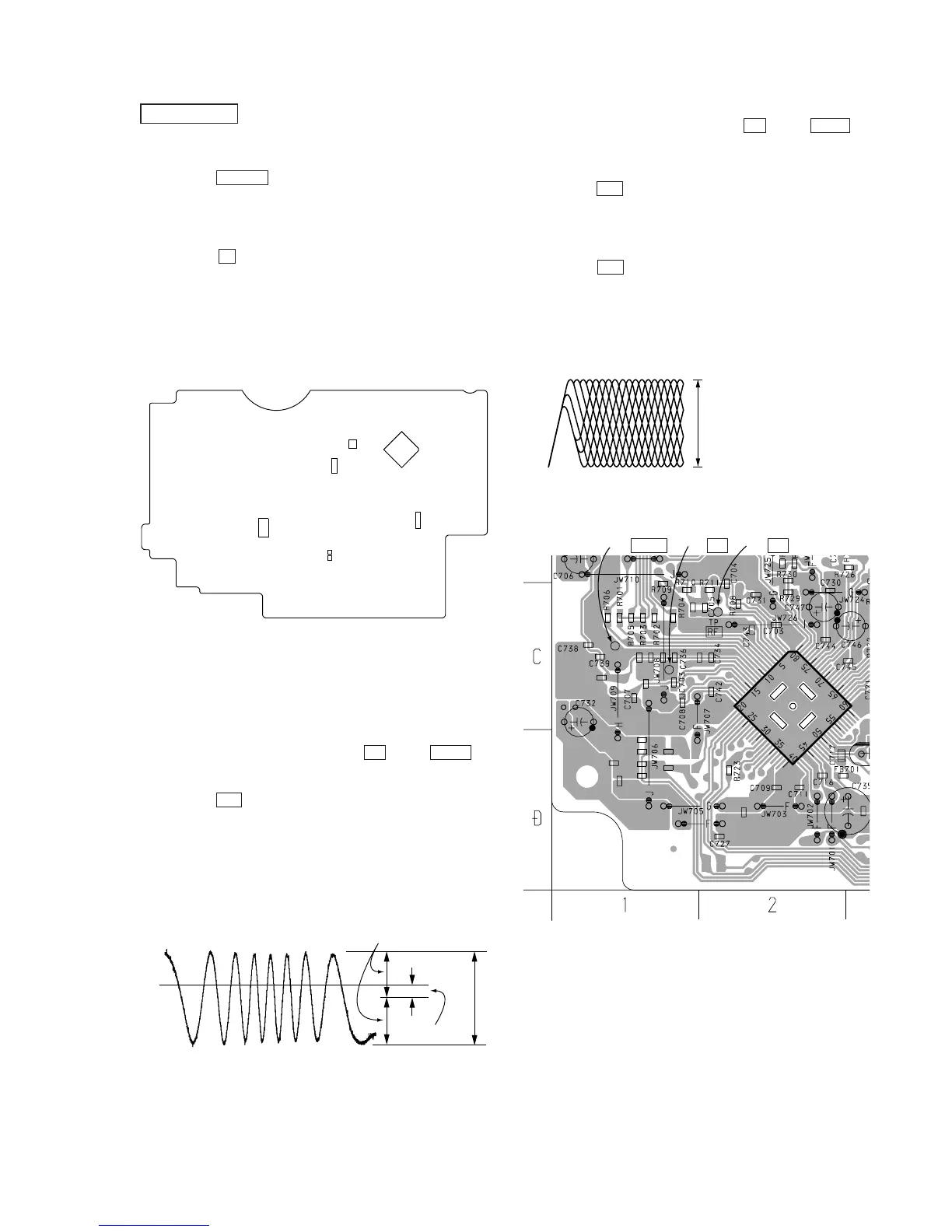
[MAIN BOARD] (Conductor side)
Traverse Waveform Check
1. Connect an oscilloscope between TP TE and TP VREF on
CD board.
2. Set the CD test mode.
3. Press the u botton to play the test disc (YEDS-18).
4. Confirm that the center of the traverse waveform will be at 0V.
5. Confirm that the peak-to-peak voltage value of the traverse
waveform meets the specification.
6. Release the CD test mode.
• Traverse waveform
A (DC voltage)
symmetry
0V
A = 0
±
220 mV
B = 0.95
±
0.55 Vp-p