– 8 –
PRECAUTION
1. Clean the following parts with a denatured alcohol-moistened
swab :
record/playback head pinch roller
erase head rubber belts
capstan idlers
2. Demagnetize the record/playback head with a head demagne-
tizer. (Do not bring the head demagnetizer close to the erase
head.)
3. Do not use a magnetized screwdriver for the adjustments.
4. After the adjustments, apply suitable locking compound to the
parts adjusted.
5. The adjustments should be performed with the rated power
supply voltage unless otherwise noted.
Torque Measurement
Mode Torque meter Meter reading
Forward CQ-102C
25 – 60 g • cm
(0.35 – 0.83 oz • inch)
Forward
CQ-102C
1 – 5 g • cm
back tension (0.014 – 0.069 oz • inch)
Fast
CQ-201B
55 – 140 g • cm
Forward (0.76 – 1.94 oz • inch)
Rewind CQ-201B
55 – 140 g • cm
(0.76 – 1.94 oz • inch)
Tape Tension Measurement
Mode Tension meter Meter reading
Forward CQ-403A
more than 170 g
(more than 6.00 oz)
SECTION 4
ELECTRICAL ADJUSTMENTS
SECTION 3
MECHANICAL ADJUSTMENTS
4-1. TAPE SECTION 0 dB = 0.775 V
Standard Output Level
Output terminal HP OUT
load impedance 32 Ω
output signal level 0.25 V (–10 dB)
Test Tape
Type Signal Used for
WS-48A 3 kHz, 0 dB tape speed adjustment
P-4-A063 6.3 kHz, –10 dB head azimuth adjustment
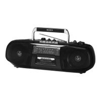
Tape Speed Adjustment
Procedure:
Mode: playback
Adjustment Value:
Digital frequency counter
2,970 – 3,030 Hz
Frequency difference between the beginning and the end of the tape
should be within 1.5% (45 Hz).
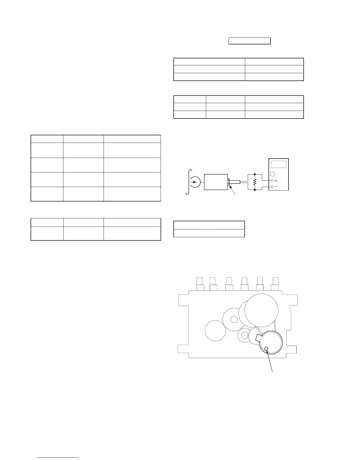
Adjustment Location:
0000
phones jack
digital frequency
counter
set
32
Ω
test tape
WS-48A
(3 kHz, 0 dB)
tape speed adjustment
control inside motor
 Loading...