DCR-PC1000/PC1000E
2-1 2-2
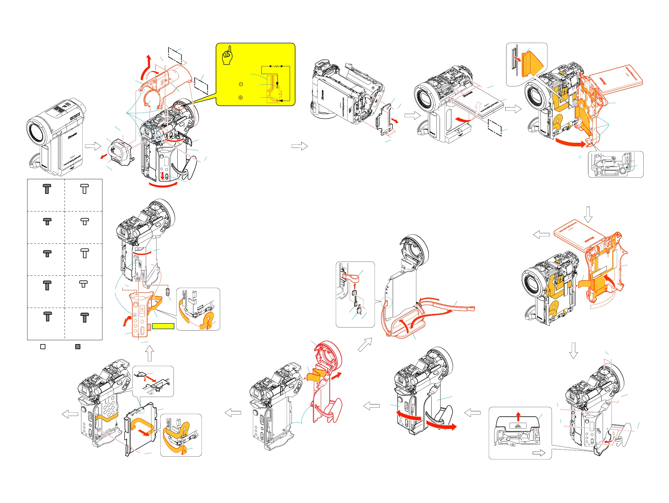
2-1. DISASSEMBLY
The following flow chart shows the disassembly procedure.
2. DISASSEMBLY
A
A
A
B
B
A
A
A
7
8
3
1
2
5
B
A
A
C
2
1
2
3
1
1
2
1
2
D
3
4
9
0
qd
6
qa
qs
a
b
3
B
4
F
5
E
6
E
E
3
2
1
1
2
Lens side
a
b
a
b
1
Slide the eject knob in the
direction of the arrow a.
2
Open the cassette lid.
3
Screw (M1.7x4) (Black)
4
Open the jack cover.
5
Screw (M1.7x4) (Black)
6
Open the shoe cover.
7
Screw (M1.7x4) (Black)
8
TB cabinet assembly
9
Screw (M1.7x4) (Black) (Silver)
0
Screw (M1.7x4) (Black) (Silver)
qa
Two screws (M1.7x4) (Black)
qs
Two claws
qd
Remove the TU cabinet assembly
in the direction of the arrow b.
qf
Microphone (4P)
1
Screw (M1.4x2.5) (Black)
2
Three screws (M1.7x4) (Black)
3
Remove the cabinet (B) assembly.
1
Open the LCD panel.
2
Screw (M1.7x4) (Black) (Silver)
3
Three screws (M1.7x2.5) (Silver)
1
Unlock by pressing the switch in the deep end of the hole.
2
Open the cabinet (R) assembly in the direction
of the arrow rotate 45
°
.
3
FP-164 flexible board (80P)
1
Open the cabinet (R) assembly in the direction
of the arrow.
2
FP-168 flexible board (39P)
1
Close
the cassette lid in the direction
of the arrow a.
2
Open the cabinet (G) assembly
in the direction of the arrow. b
1
Claw
2
Remove the front block assembly
in the direction of the arrow.
3
FP-169 flexible board (20P)
B
Hinge section
(See page 2-3)
Strob section
(See page 2-3)
1
Slide the battery lid in the direction of the arrow a,
and open it in the direction of the arrow b.
2
Two screws (M1.7x2.5) (Black)
3
Screw (M1.7x2.5) (Black)
4
Two screws (M1.7x4) (Silver)
5
Tapping screw (M1.7x3.5) (Silver)
6
Screw (M1.7x2.5) (Black)
H
2
4
3
1
1
FP-170 flexible board (10P)
2
Screw (M1.4x1.5) (Silver)
3
Claw
4
Remove the cabinet (battery)
in thedirection of the arrow.
A
G
G
5
7
8
3
4
6
1
2
1
Control switch block (PS11800) (16P)
2
Remove the control switch block (PS11800) (16P)
3
Open the cassette lid.
4
Screw (M1.7x4) (Black)
5
Screw (M1.7x4) (Black)
6
Claw
7
Remove the control switch block (PS11800)
in the direction of the arrow.
8
Eject knob
1
Open the grip in the direction of the arrow a.
2
Remove the belt in the direction of the arrow b.
3
Remove the belt assembly in the direction of the arrow c.
4
Two tapping screw (M1.7x3.5) (Silver)
5
Plate
6
Belt fixed plate (rear)
7
Grip belt (PC)
F
4
23
1
6
5
7
a
b
c
HELP 01
Silver
Black
Tapping screw
M1.7x3.5
3-078-890-01
F
Screw
M1.4x2.5
3-086-368-11
C
Screw
M1.7x2.5
3-989-735-01
D
Screw
M1.7x4
3-084-817-31
G
Screw
M1.4x1.5
3-062-214-01
I
Screw
M1.7x4
3-087-376-01
A
Screw
M1.7x4
3-056-030-91
B
Screw
M1.7x2.5
3-084-817-11
E
Tapping screw
M1.7x5
3-080-204-21
H
Tapping screw
M1.7x3.5
3-080-204-01
J
qg
Discharging the capacitor
Caution
FL11800
Short jig (
1k
Ω
/1W
)
Hole of
terminal
Hole of
terminal
qf
2
3
1
Three claws
Ver 1.1 2005. 05