Chapter 2 Location and Function of
Parts and Controls
Chapter 2 Location and Function of Parts and Controls 2-13
Processor Unit
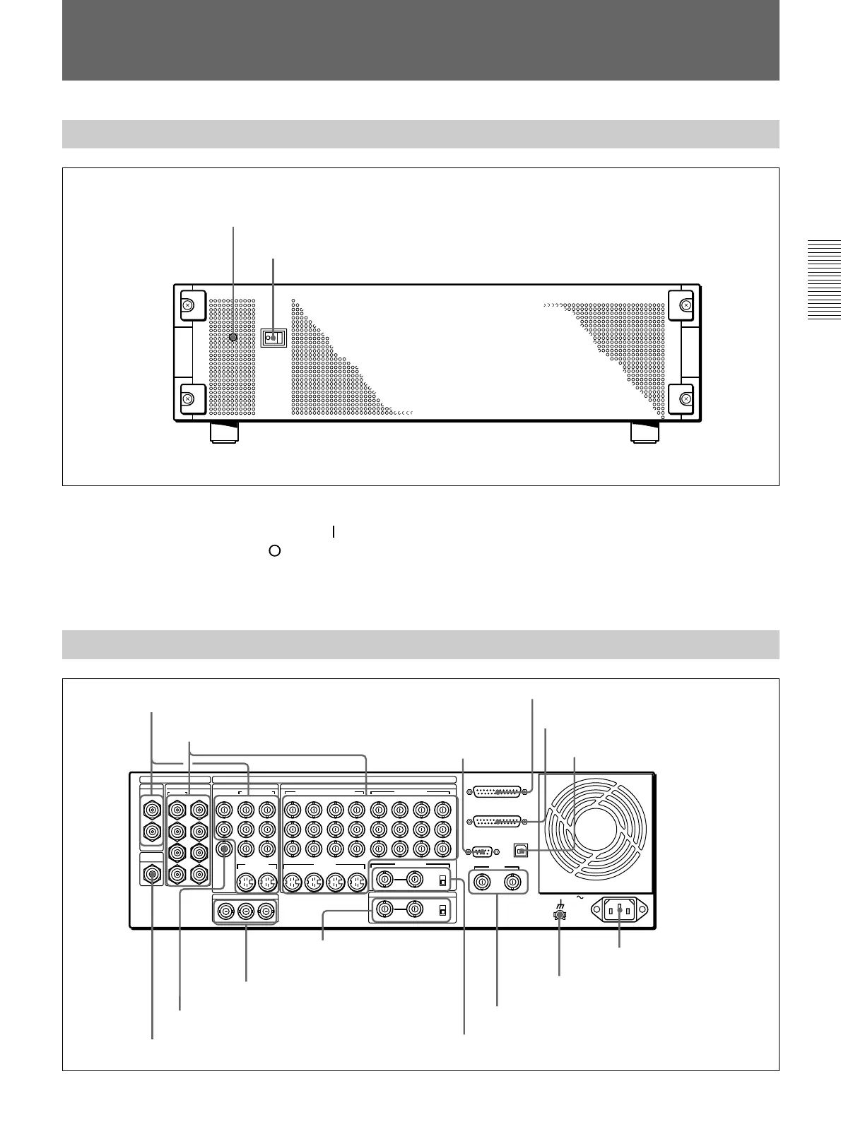
Front Panel
Power indicator
Power switch
Power switch and indicator
This powers the unit on and off. Press the “
” side of
the switch to power on, and the “
” side to power off.
When the power is on, the power indicator lights
amber.
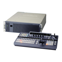
Rear Panel
1 PGM OUT connectors
1
3
1
2
1
2
2
1
3
4
5
6
7
8
21
Y
COMPOSITE
PGM OUT
CLEAN
OUT
OPTION
SDI INPUT PGM OUT
BLACK BURST OUT
VIDEO INPUT
COMPONENT
S VIDEO
COMPONENT/COMPOSITE COMPONENT
DIGITAL I/O
ANALOG I/O
AC IN
2
R-Y
PVW
B-Y
65
Y/V
R-Y
B-Y
87 6/2 5/1
Y
R-Y
B-Y
8/4 7/3
2 1
REF.VIDEO IN
GPI/T
PANEL
TALLY
EDITOR
TERMINAL
DSK KEY IN
ON
OFF
OFF
75Ω
ON
75Ω
8 7 6 5
S VIDEO
(OPTION)
(OPTION)
2 1
2 VIDEO INPUT connectors
3 EDITOR
connector
4 PANEL connector
5 TALLY connector
6 TERMINAL connector
7 CLEAN OUT connector
8 PVW connector
9 BLACK BURST OUT 1 to 3
connectors
q; DSK KEY IN connectors
and 75Ω terminator
switch
qa REF. VIDEO IN connectors and 75Ω
terminator switch
qs GPI/T 1 and 2 connectors
qd U terminal
qf - AC IN connector