Do you have a question about the Sony DSC-T77 and is the answer not in the manual?
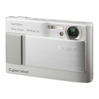
Details about the camera's image device, lens, exposure control, white balance, file format, recording media, and flash.
Lists multi-connector functions like video/audio output and USB communication.
Details the LCD panel size, type, and resolution.
Covers power source, consumption, operating/storage temperature, dimensions, and mass.
Details power requirements, output voltage, operating temperature, dimensions, and mass of the battery charger.
Lists battery type, maximum/nominal voltage, and capacity.
Steps to ensure safety after service, including checking connections and component condition.
Explains characteristics and usage of unleaded solder, including its melting point and viscosity.
Notes on handling destination data, USB serial number, and angular velocity sensor sensitivity for SY-207 board replacement.
Guidance on recording PITCH/YAW, FN, and wide limit data when replacing the lens.
Instructions for copying or formatting data within the camera's internal memory.
Steps to enable and perform data writing to the camera's internal memory from a PC.
Explains how the self-diagnosis function operates and displays information when problems occur.
Describes the 4-digit alphanumeric display indicating repair status, problem block, and detailed code.
A table listing self-diagnosis codes, symptoms, and corresponding corrections for troubleshooting.
Instructions for initializing settings to clear the flash error code after repair.
Important precautions for handling flat cables, flexible boards, and connectors during repair.
Instructions for safely discharging high-voltage capacitors on the ST-199 flexible board.
Steps to prepare a short jig for discharging capacitors, including necessary components and insulation.
Exploded view of the camera, identifying major component blocks and flexible boards.
Outlines the disassembly process for overall, main, and ST/rear sections.
Detailed steps for disassembling the front block, including specific part numbers and cautions.
Detailed steps for disassembling the lens block, SY-207 board, and BT lid base with part references.
Detailed steps for disassembling the ST-199 flexible board and LCD block, with specific cautions and part references.
Provides cautions for installing the LCD block, focusing on claw engagement and bezel fitting.
Details the method for folding and attaching the ST-199 flexible board to the ST holder.
Provides notes and cautions for attaching the BT hinge shaft, emphasizing care during insertion.
Notes on assembling the front block, focusing on bending claws and securing bosses for proper engagement.
First part of the overall block diagram illustrating system connections and components.
Second part of the overall block diagram, continuing the system connections and components.
First part of the power block diagram, showing power distribution and related circuits.
Second part of the power block diagram, detailing power distribution and related circuits.
Schematic diagram for the ST-199 flexible board, detailing flash drive circuitry.
Schematic diagram for the BT-044 flexible board, detailing battery and playback switch circuits.
Schematic diagram for the control switch block, detailing its functions.
General notes and conventions applicable to all schematic diagrams in the manual.
Precautions and procedures for replacing the imager, including static electricity handling.
Printed wiring board layout for the ST-199 flexible board.
Printed wiring board layout for the BT-044 flexible board.
General notes and conventions applicable to printed wiring boards.
Exploded view showing the overall assembly of the camera.
Exploded view showing the main internal components of the camera.
Exploded view showing the ST/rear section components.
Electrical parts list for the BT-044 flexible board.
Electrical parts list for the ST-199 flexible board.
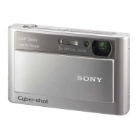
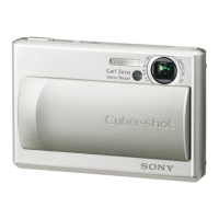
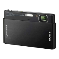
| Lens | Carl Zeiss Vario-Tessar |
|---|---|
| Optical Zoom | 4x |
| Image Stabilization | Optical SteadyShot |
| Dimensions | 93.6 x 57.2 x 15.0 mm |
| Digital Zoom | 8x |
| Optical Sensor Size | 1/2.3 inch |
| Shutter Speed | 1/4 - 1/1000 sec |
| Sensor | 1/2.3 type Super HAD CCD |
| Display | 3.0-inch TFT LCD |
| Video Recording | 640 x 480 (30 fps) |
| Storage | Memory Stick Duo/PRO Duo |
| Battery | NP-BD1 |
| Image Sensor | 10.1 Megapixels |
| ISO Sensitivity | 80-3200 |