5-66
3. Battery End Adjustment
Set the battery end voltage.
If the voltage is incorrect, the life of the battery will shorten.
The image at the battery end will also be rough.
Mode Camera recording
Subject Arbitrary
Measurement Point Display data of page: 2, address: 5E
Measuring Instrument Adjustmemt remote commander
Adjustment Page D
Adjustment Address F0 to F6, F8 to FE
Switch setting:
1) AUTO...............................................................................OFF
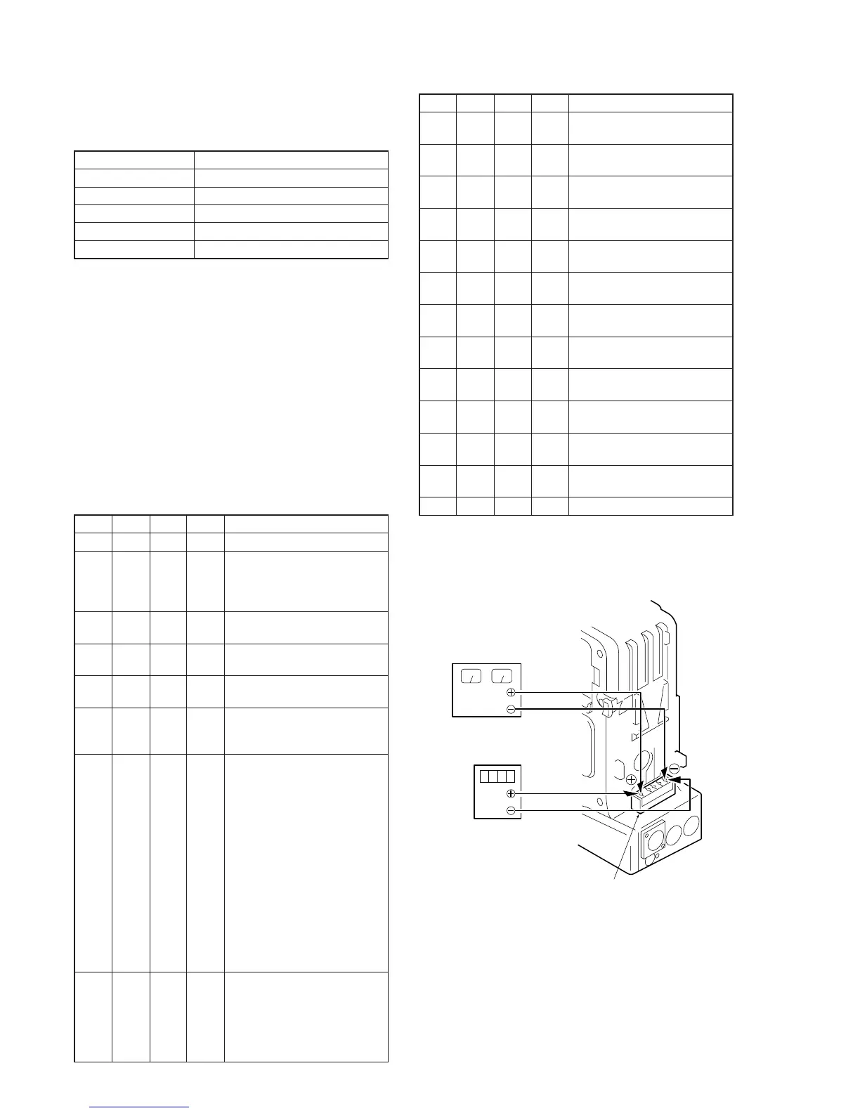
Connection:
1) Connect the regulated power supply and the digital voltmeter
to the battery terminal as shown in Fig. 5-3-4.
Preparations before adjustments:
1) Adjust the output voltage of the regulated power supply so that
the digital voltmeter display is 11.0 ± 0.1Vdc.
2) Turn off the power supply.
3) Turn on the HOLD switch of the adjustmemt remote
commander.
4) Turn on the power supply.
5) Load a cassette, and set to the camera recording mode.
Adjusting method:
Order Page
Address
Data Procedure
1 0 01 01 Set the data.
2 Adjust the output voltage of the
regulated power supply so that
the digital voltmeter display is
11.00 ± 0.01Vdc.
3 2 5E Read the data, and this data is
named Dref.
4 D F0 Dref Set the data, and press PAUSE
button.
5 D F8 Dref Set the data, and press PAUSE
button.
6 Convert Dref to decimal
notation, and obtain Dref’.
(Note1)
7 Calculate DF1’ to DF6’ and
DF9’ to DFE’ using following
equations. (decimal calculation)
DF1’=Dref’+4
DF2’=Dref’+5
DF3’=Dref’+12
DF4’=Dref’+31
DF5’=Dref’+46
DF6’=Dref’+62
DF9’=Dref’+4
DFA’=Dref’+5
DFB’=Dref’+8
DFC’=Dref’+12
DFD’=Dref’+16
DFE’=Dref’+23
8 Convert DF1’, DF2’, DF3’, DF4’,
DF5’, DF6’, DF9’, DFA’, DFB’,
DFC’, DFD’ and DFE’ to decimal
notation, and obtain DF1, DF2,
DF3, DF4, DF5, DF6, DF9, DFA,
DFB, DFC, DFD and DFE. (Note1)
Order Page
Address
Data Procedure
9DF1DF1 Set the data, and press PAUSE
button.
10 D F2 DF2 Set the data, and press PAUSE
button.
11 D F3 DF3 Set the data, and press PAUSE
button.
12 D F4 DF4 Set the data, and press PAUSE
button.
13 D F5 DF5 Set the data, and press PAUSE
button.
14 D F6 DF6 Set the data, and press PAUSE
button.
15 D F9 DF9 Set the data, and press PAUSE
button.
16 D FA DFA Set the data, and press PAUSE
button.
17 D FB DFB Set the data, and press PAUSE
button.
18 D FC DFC Set the data, and press PAUSE
button.
19 D FD DFD Set the data, and press PAUSE
button.
20 D FE DFE Set the data, and press PAUSE
button.
21 0 01 00 Set the data.
Note1: Refer to Table 5-4-1. “Hexadecimal-decimal conversion table” of
“5-4.Service mode”.
Regulated power
supply (11.0
±
0.01Vdc)
Digital voltmeter
Battery terminal
Fig. 5-3-4.
 Loading...