5-70
3-4. VIDEO SYSTEM ADJUSTMENTS
Before perform the video system adjustments, check that the
specified value of “27MHz Origin Oscillation Adjustment” of
“CAMERA SYSTEM ADJUSTMENT” is satisfied.
3-4-1. Base Band Block Adjustments
1. Chroma BPF f0 Adjustment (VI-156 board)
Set the center frequency of IC1301 chroma band-pass filter.
Mode Camera
Subject All black
(Cover the lens with the lens cap)
Measurement Point CH1: Chroma signal terminal of
S VIDEO jack (75Ω terminated)
CH2: Y signal terminal of S VIDEO
jack (75Ω terminated)
Measuring Instrument Oscilloscope
Adjustment Page C
Adjustment Address 28
Specified Value A = 100mVp-p or less
B = 200mVp-p or more
Adjusting method:
Order Page
Address
Data Procedure
1 0 01 01 Set the data.
2 Check that the burst signal (B) is
output to the chroma signal
terminal of S VIDEO jack.
3 3 0C 04 Set the data, and press PAUSE
button.
4 C 28 Change the data for minimum
amplitude of the burst signal
level (A).
(The data should be “00” to
“07”.)
5 C 28 Press PAUSE button.
6 3 0C 00 Set the data, and press PAUSE
button.
7 Check that the burst signal level
(B) satisfies the specified value.
8 0 01 00 Set the data.
2. S VIDEO OUT Y Level Adjustment (VI-156 board)
Mode Camera
Subject Arbitrary
Measurement Point Y signal terminal of S VIDEO jack
(75Ω terminated)
Measuring Instrument Oscilloscope
Adjustment Page C
Adjustment Address 25
Specified Value A = 1000 ± 14mV
Adjusting method:
Order Page
Address
Data Procedure
1 0 01 01 Set the data.
2 2 35 Note down the data.
3 2 35 01 Set the data.
4 3 0C 02 Set the data, and press PAUSE
button.
5 C 25 Change the data and set the Y
signal level (A) to the specified
value.
6 C 25 Press PAUSE button.
7 3 0C 00 Set the data, and press PAUSE
button.
8 2 35 Set the data that is noted down at
step 2.
9 0 01 00 Set the data.
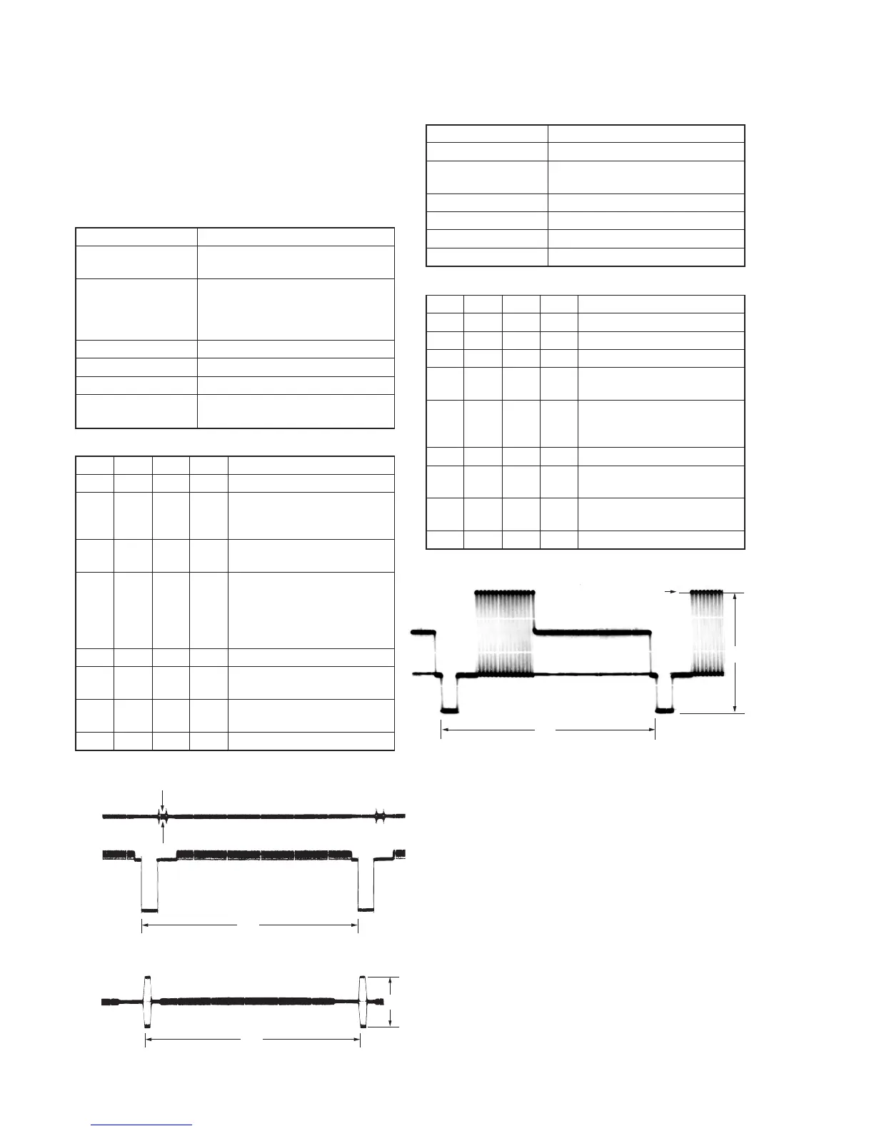
CH1
CH2
A
H
CH1
H
B
When the data of page: 3, address: 0C, is 04:
When the data of page: 3, address: 0C, is 00:
Fig. 5-3-7.
H
Center of luminance line
A
Fig. 5-3-8.
 Loading...