5-80
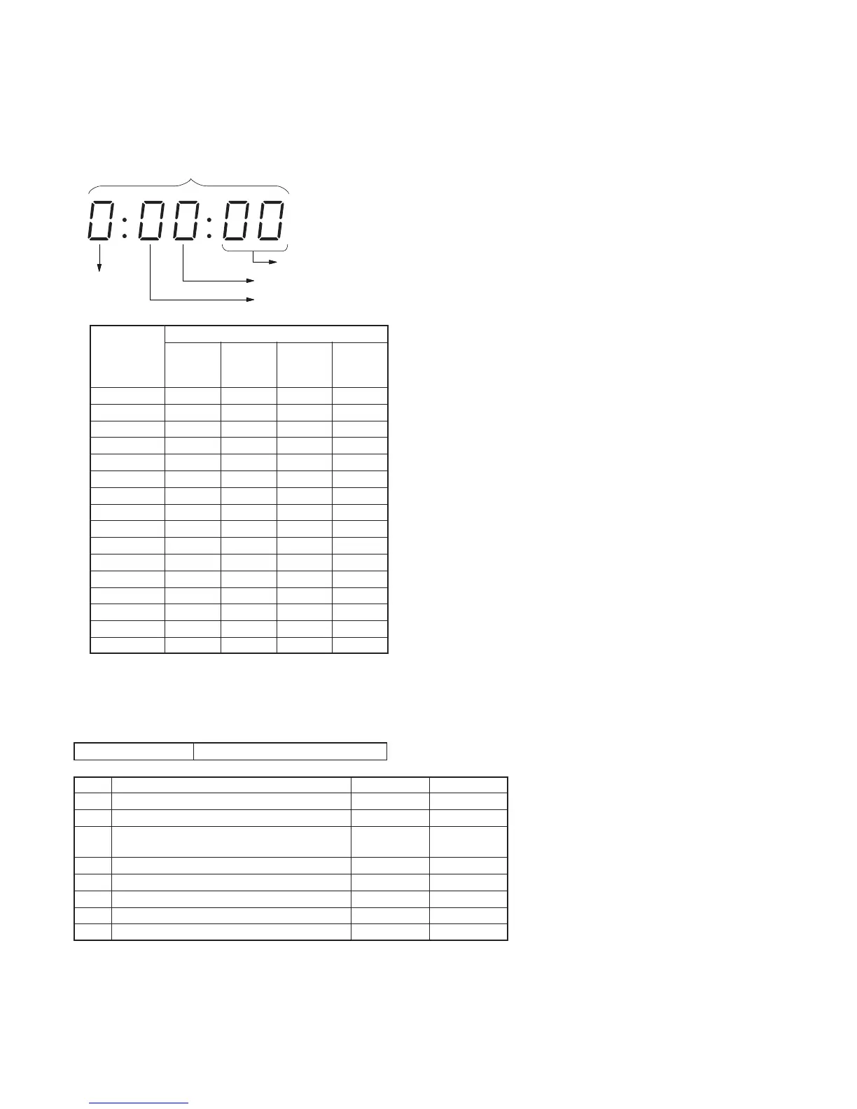
Display on the
adjustment
remote
commander
0
1
2
3
4
5
6
7
8
9
A (
A
)
B (
b
)
C (
c
)
D (
d
)
E (
E
)
F (
F
)
Bit values
bit3
or
bit7
0
0
0
0
0
0
0
0
1
1
1
1
1
1
1
1
bit2
or
bit6
0
0
0
0
1
1
1
1
0
0
0
0
1
1
1
1
bit1
or
bit5
0
0
1
1
0
0
1
1
0
0
1
1
0
0
1
1
bit0
or
bit4
0
1
0
1
0
1
0
1
0
1
0
1
0
1
0
1
B
Example: If “8E” is displayed on the adjustment remote commander, the
bit values for bit7 to bit4 are shown in the A column, and the
bit values for bit3 to bit0 are shown in the B column.
Page
Address
bit3 to bit0 discrimination
bit7 to bit4 discrimination
Display on the adjustment remote commander
3. Bit value discrimination
Bit values must be discriminated using the display data of the
adjustment remote commander for following items. Use the table
below to discriminate if the bit value is “1” or “0”.
4. Switch check (1)
Page 2 Address 43
Bit
0
1
2
3
4
5
6
7
Function
VTR MODE SW (PM-040 board S081)
CAMERA MODE SW (PM-040 board S081)
START/STOP SW
(FS-082 board S402, CF-1044 block S432)
EJECT SW (EJ-034 board S291)
CC DOWN SW (Mechanism chassis)
PHOTO FREEZE SW (CF-1044 block S431)
MEMORY MODE SW (PM-040 board S081)
When bit value=1
OFF
OFF
OFF
OFF
OFF (UP)
OFF
OFF
When bit value=0
ON
ON
ON
ON
ON (DOWN)
ON
ON
Using method:
1) Select page: 2, address: 43.
2) By discriminating the bit value of display data, the state of the switch can be discriminated.
A

 Loading...