2-46
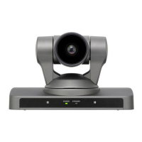
EVI-HD7V
2-4-2. Adjusting Procedure
1. Preparation
(1) Connect a personal computer and a camera with a VISCA cable.
n
When setting the camera, make sure to set it on the stable place at a level surface.
Also, be careful that the pan and tilt operation are not interfered by an obstruction.
(2) Turn on the power of a camera.
(3) Start up VISCA communication software.
(4) The motor may malfunction with a strong rattle when the power is turned on after the pan motor or
tilt motor is replaced and reassemble. To prevent this, send the following command from the VISCA
communication software before disassembling it. (The tilt motor may malfunction with rattling only
by loosening the shaft securing screw even when it is not replaced.)
. Transmission at 8101062213FF (Receiving of debug command enabled)
Commands of 9041FF and 9051FF are returned to Response Window.
. Transmission at 8101061F03FF (Receiving of adjustment command enabled)
Commands of 9041FF and 9051FF are returned to Response Window.
. Transmission at 8101060CFF (Clearing of hall sensor data)
Commands of 9041FF and 9051FF are returned to Response Window.
n
When nothing is displayed on Response Window after the command is sent (message is not returned),
check the connection of cable and the camera condition.
2. Pan/Tilt adjustment
Perform transmission of VISCA command and adjustment according to the following procedure.
Type each command to DirectCommand window of the communication software, and then press Enter
key to transmit the each command.
(1) Transmission at 8101062213FF (Receiving of debug command enabled)
Commands of 9041FF and 9051FF are returned to Response Window.
(2) Transmission at 8101061F03FF (Receiving of adjustment command enabled)
Commands of 9041FF and 9051FF are returned to Response Window.
(3) Pan and tilt are stayed at the following position.
Pan: Left end (DC IN terminal side)
Tilt: Lower end
n
If the data is not written in EEPROM of the SY-359 board, Pan and Tilt are not controlled (freely
rotates). Therefore, place the camera head in the position of step (3), and then perform step (4). If
EEPROM is already written, Pan and Tilt stop at the HOME position or the preset 1 storing position.
Therefore, perform step (4) as it is.
In this case, an adjustment error may occur due to the individual variability. After the occurrence of
error, Pan and Tilt are not controlled. Therefore, stay the camera head in the position of step (3) and
perform the adjustment from step (1) again.
(4) Transmission at 81010609FF (Adjustment starts)
Command of 9041FF is returned to Response Window.
After this, pan and tilt operate automatically, and then DC level and amplitude of a MR sensor, and
positions of a reset sensor and mechanical termination point are measured.

 Loading...