GTK-XB72
11
Sony CONFIDENTIAL
For Authorized Servicer
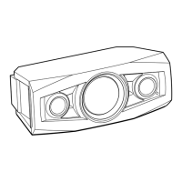
2-4. SIDE PANEL ASSY BLOCK-2 (RIGHT SIDE)
top side
rear side
right side
bottom side
boss
(with bond)
1 Grasp the smartphone holder
portion, lift up the side panel
assy (right) block from the
rear side.
2 Lift up the side panel assy (right)
block, remove five bosses so as
to draw out from the speaker
cabinet gradually.
total five bosses
(with bond)
3 Lift up the side panel assy (right) block
until the sound that hook disengages
is heard and remove eight hooks.
5 Remove the side panel
assy (right) block in the
direction of the arrow.
6 FFC (KL-RA and KR-RA)
(XP6) (12 core)
8 side panel assy (right) block
terminal
side
smartphone
holder
total five bosses
total five holes
– Inner view –
– right view –
bottom side
top side
Note 2:
When installing the side panel assy (right) block,
remove cleanly the sticked bond on bosses and
holes and apply bond to the side panel assy
(right) block again and install it.
Hot to install the side panel assy (
right) block
4 Lower the side panel
assy (right) block.
total eight hooks
hole
7 Draw the FFC (KL-RA and KR-RA)
out of the hole on the top bracket.
When the side panel assy (right) cannot be lifted up
When the side panel assy (right) cannot be lifted up, insert a jig into gap
between side panel assy (right) and speaker cabinet, lift up a jig gradually,
and draw out the boss on the side panel assy (right) from the speaker cabinet.
boss
(with bond)
soft cloth, etc.
Note 3:
When working with the left side
facing down, lay a soft cloth, etc.
so as not to damage.
Note 1:
Work slowly so an not to damage the side panel assy (right) with a jig.
SYSSET
2019/01/1806:06:34(GMT+09:00)

 Loading...