GTK-XB90
10
2-8. MAIN BOARD
7 Remove the MAIN board
block in the direction of
the arrow.
5 screw
(M3 u 10)
4 POWER board cable
connector (XP20)
left side
right side
rear side
rib
thermal sheet
hole
9 MAIN board
Note 2:
When installing the MAIN board,
align the rib and hole.
• Wire setting
MAIN
board
– Top view –
hook
hook
FFC
(TOP LED-MAIN)
XP11
XP13
XP7
A
A
B
B
2 woofer cable connector
(XP13)
1 tweeter cable connector
(XP11)
3 FFC (TOP LED-MAIN)
(XP7)
terminal side
6 four screws
(3 u 6)
8 thermal sheet
(See Fig. B)
tweeter cable
woofer cable
rear side
XP20
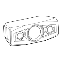
< Fig. B >
• Pasting position of the thermal sheet
When affixing the thermal sheet, affix so that the hole
of the shassis’s projection block is filled.
left side
rear side
hole
shassis
projection
block
Note 1: The MAIN board for AEP, UK has been changed in the mid-
way of production. Before replacing the defective MAIN board
with the new MAIN board, be sure to refer to “CHANGE OF
MAIN BOARD (AEP, UK only)” on page 5 and check the se-
rial number, and distinguish the before changing (Former type)
and after changing (New type).
Ver. 1.4
SYSSET
2020/08/2022:42:53(GMT+09:00)

 Loading...