GTK-XB90
9
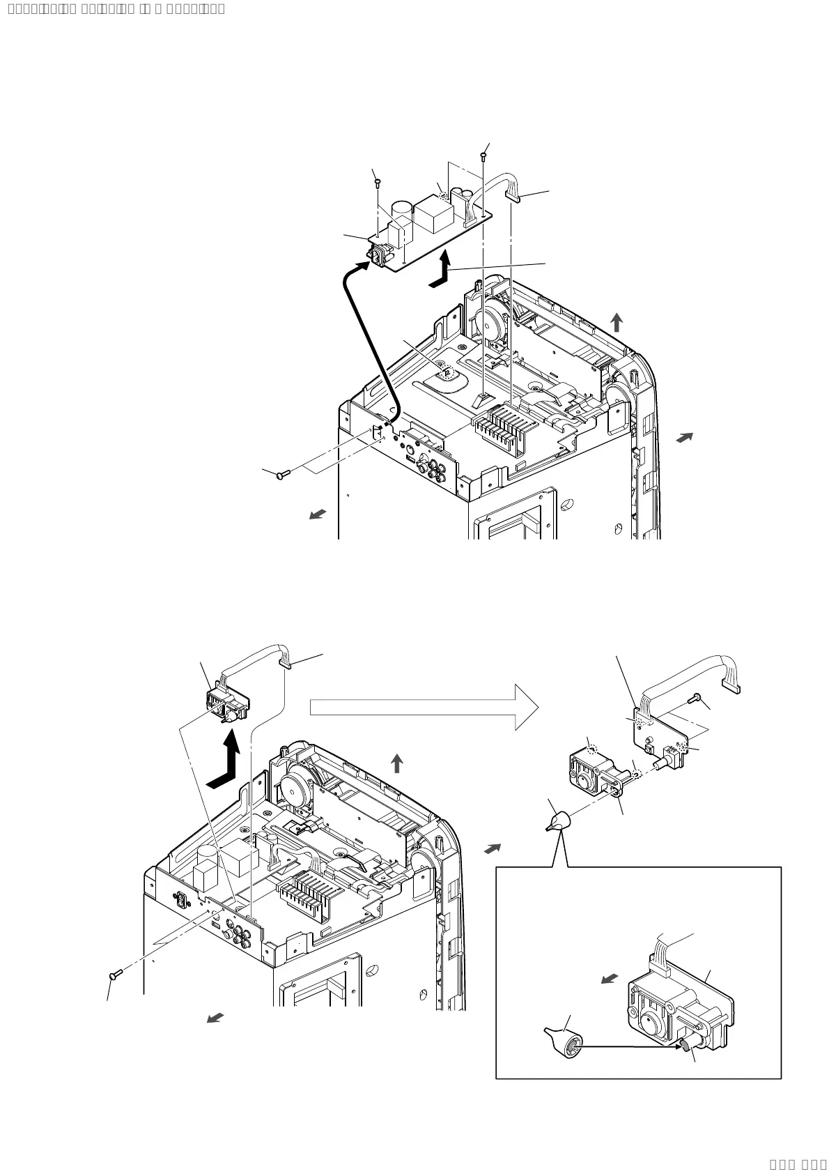
2-6. POWER BOARD
2-7. MIC KNOB BOARD
hole
rib
5 POWER board
Note:
When installing the POWER
board, align the rib and hole.
3 two screws
(3 u 6)
3 two screws
(3 u 6)
2 two screws
(M3 u 10)
rear side
1 POWER board cable
connector (XP20)
front side
top side
4 Remove the POWER board
in the direction of the arrow.
5 two screws
(M3 u 10)
2 two screws
(M3 u 10)
1 MIC KNOB board cable
connector (XP4)
4 MIC knob
MIC KNOB
board block
How to install the MIC knob
When installing the MIC knob to the rotary encoder,
align the directions of the D-shaped tip of the rotary
encoder and the D-shaped notch at the inner side
of the MIC knob.
MIC knob
rotary encoder
rear side
front side
top side
3 MIC KNOB board block
6 key unit
hole
boss
boss
hole
7 MIC KNOB board
Note:
When installing the MIC KNOB board,
align the two bosses and two holes.
rear side
SYSSET
2020/08/2022:42:53(GMT+09:00)

 Loading...